PavLab Photos/Events
- MechE News/March2025
- 2.680 Spring 2024
- Jervis Bay 2023
- Aug 23rd 2023
- Aug 3rd 2023
- Open House 2022
- Photo Archives
Current Lab Robots
Current Projects
- MOOS-IvP
- Swarm Toolbox
- HydroMAN
- MIT Sea Beaver UUV
- USV Model Estimation
- MOOS-IvP-Multi
- Blueboat Autonomy
- Spurdog UUV
- Skywalker
- DARPA LINC
- Stochastic Ray Trace
- MTASC
- Advanced COLREGS
Current UGrad Projects


Robot Archives
Project Archives
- Swarm Declustering
- PBACS
- Prodromos
- RoboWhaler
- Autonomous Fish Finding
- Sea Train
- Multi-Arch Autonomy
- Morpheus
- HydroLink Buoy
- Perseus
- IITCHS
- Remote Explorer IV
- Aquaticus
- Charting the Charles
- Boston Harbor RoboChallenge
- COLREGS Autonomy
- ICEX 2016/2020
The PABLO Box
Maintained by: mikerb@mit.edu  Get PDF
1 The PABLO Box
2 Payload Autonomy
2.1 Emulation
2.2 What is Pablo?
3 Pablo Design
3.1 Enclosure
3.1.1 Water intrusion
3.1.2 Housing selection
3.2 Power Inputs
3.2.1 Power requirements
3.2.2 Voltage regulators
3.3 Computing
3.3.1 Size Requirements
3.3.2 Computing Platform Selection and Alternatives
3.3.3 Connectors
3.3.4 Gland selection
3.4 Interior Mounting
4 Network Topology
4.1 Network Topology Overview
4.1.1 MOOS Simulations and the IP Network
4.1.2 Network Topology Without Payload Autonomy
4.1.3 Network Topology for Payload Autonomy
4.1.4 Network Topology for Vehicle Emulation with Payload Autonomy
5 Network Configuration
5.1 Initial Primary Router Configuration
5.2 Field Wireless Radio Configuration
5.3 M200 Vehicle Network Configuration
5.3.1 PABLO Network Configuration
5.3.2 Additional Primary Router Configuration
5.4 Pablo Computer Preparation
5.4.1 Raspi TFT Display - Software Configuration and Hardware Setup
5.5 Pablo Assembly Instructions
5.6 Enclosure Preparation
6 Mounting Plate
6.1 Installing the Raspi
1 The PABLO Box
Commercially-available robotic vessels generally include a computing system with hooks for autonomous control. At the most basic level, the integral controller interfaces with some steering/throttle input and conveys commands to on-board control surfaces. In addition, some vehicles include navigation sensors and health monitors that are integrated with the on-board computer. More sophisticated commercial vehicles are provided with some level of autonomy on-board, onsuming the navigation sensor data to make ation decisions.
The on-board vehicle-control computer is referred to as the front-seat. An interface exists that receives input commands from outside to be interpreted as vehicle control. The interface outputs available status, navigation, and health data. Methods and format for the bi-directional data stream is called a wire protocol. The front-seat can be considered a black box with data flow managed through the wire protocol.
The back-seat is an entity that implements the wire protocol to communicate with the front-seat. On some systems, the front-seat computer is open and requires that the back-seat software share the hardware. For example, the first generation Clearpath Kingfisher M100 included an on-board computer without a payload bay. There are advantages to separating the back-seat onto a dedicated computer. In fact, front-back separation is a hallmark of payload autonomy.
In the front/back-seat paradigm, integrating MOOS-IvP onto a vessel means passing decisions about heading and speed (or steering angle and throttle position) to the front-seat for vehicle control while receiving navigation signals in return. The wire protocol is implemented in a dedicated driver application in MOOS. For example, the Clearpath Kingfisher M200 vehicle is interfaced with the iM200 application, which handles details of pushing commands and parsing incoming pose, position, and health messages.

2 Payload Autonomy
Payload autonomy is a paradigm for controlling an autonomous vehicle where the autonomy software operates from a dedicated and removable back-seat computer. A separate front-seat system manages vehicle control and low-level sensing. The back-seat computer connects physically through a payload port (usually Ethernet, sometimes serial) and logically using a wire protocol. The Pablo Box for the Kingfisher M200 is an example of a payload autonomy system.
Unmanned marine vehicle front-seat systems are often a full computer with an operating system and the ability to log in and install user code. Alternatively, the front-seat may be a simple device like an Arduino with no OS. Historically at MIT, MOOS-IvP code was installed and executed on the OEM computing device. However, this arrangement is inconvenient for various reasons:
- Front-seat integrity. Preparing a MOOS mission requires access to the physical vehicle for updating software and files, installing dependencies, and building custom code. This effort is then duplicated on each physical vehicle. It is possible that these steps are incompatible with the computing resources required by the OEM front-seat software or operating system. Furthermore, in a classroom or shared-resource setting it is not always possible to control who is accessing the front-seat computer. Students and guest researchers may inadvertently disturb system integrity.
- Ease of development. By detaching the back-seat and vehicle, a user can develop at any location and validate the code works on the back-seat hardware.
- Emulation. To further facilitate development, emulation provides a front-seat for the back-seat box.
- Modularity. A box can be configured once then moved between vehicles. The drive on a validated box can be duplicated to create multiple copies of the known working system.
- Front-seat independence. So long as the wire protocol remains constant, the manufacturer is free to modify or upgrade front-seat operations without disturbing the back-seat autonomy.
- Vehicle sharing. Hardware assets can be shared among students or researchers in a classroom or project environment without interfering with the work of others.

2.1 Emulation [top]
The ability to easily emulate the actual vehicle is a convenient feature of payload autonomy. The wire protocol insulates the back-seat from any inner workings of the vehicle. A front-seat that responds to commands and outputs the expected messages can be a physical vehicle or an emulated system. The back-seat is therefore unaware and uncaring of which one is engaged over the interface.
Here we use the term emulate to describe a black box acting as a surrogate for the entire vehicle. Simulate describes mimicking pieces of the vehicle with substitutions within a MOOS community. Our emulation system is a MOOS community running the marine simulator application uSimMarine and a module that interfaces to an Ethernet port.
2.2 What is Pablo? [top]
The Payload Autonomy Box (Pablo) unit is a dedicated back-seat computing system designed to connect with the Clearpath Robotics Kingfisher M200 vehicle. Onboard computing supports MOOS-IvP running on a GNU/Linux variant of operating system. Physically, it is designed to be splash-proof, fit within the size constrains of the M200 payload bay, and provides connection to the vehicle and user-supplied peripherals. The box design is modular and open, allowing for modifications to support other unmanned surface vehicles.
The Pablo unit is more than just hardware. Payload autonomy involves interfacing Pablo with the front seat and modifying network topology to facilitate the paradigm. Remaining sections of this document describe design and assembly of the physical unit, networking theory and practical application to payload autonomy, and details for setting up the operating system and MOOS-IvP environment on the unit.
3 Pablo Design
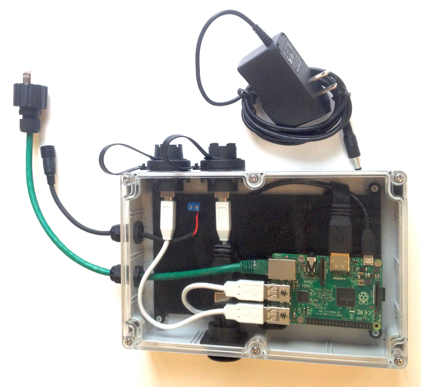
Figure 3.1: A completed PABLO unit and power supply.
The Pablo unit is a system designed by MIT to provide a back-seat payload autonomy module. The initial version was designed to interface with the hardware and wire protocols of the Clearpath Robotics Kingfisher M200 vehicle. However, the Pablo unit is modular and can be customized to fit other unmanned surface vessels.
The major requirements driving the Pablo hardware design include:
- Waterproofing. The M200 payload bay is exposed to splashing water and all system components must be protected.
- Dimensions. The M200 payload bay has limited size, some of which is constrained by connector locations. All system components must fit comfortably within the bay.
- Interfaces. The M200 exposes a single waterproof Ethernet connector that the Pablo unit must interface with.
- Power. In the office, the box must be powered from a plug-in source. On the M200, limited-current 5-volt power is available from the payload USB ports. Alternatively, a dedicated battery must be included that meets dimension requirements and can power the system for several hours.
- Peripherals. The Pablo requires additional interfaces to connect with and power user-supplied peripherals.
Based on the requirements, initial trade studies identified these key system components:
- Enclosure. A single housing that can be opened and resealed to contain system components was selected over permanent solutions such as electronics potting.
- Computing. An Arm-based, embeddable single-board computer, such as the Raspberry Pi, capable of supporting a GNU/Linux-like operating system emerged as an ideal solution over other systems such as FPGAs or larger and more powerful computing modules.
- Connectors. The payload interface connector was dictated by the existing M200 port; power and peripheral ports were investigated as described below.
- Power. Drawing power from the M200 USB ports was rejected as interfering with front-seat performance and due to limitations in power available for Pablo peripherals.
3.1 Enclosure [top]
The enclosure houses a computing system and an optional display. The box must have provisions for wiring to pass through while keeping the contents dry. As the PABLO is designed specifically for the Kingfisher M200, the box must fit completely within the vehicle's payload bay alongside a battery.
3.1.1 Water intrusion [top]
The main function of the housing is to protect the computing system from water intrusion. The PABLO unit is intended for exposure to regular splashing but not to complete submersion. Boxes with an IP67 or NEMA4 rating (or better) meet this requirement. Payload autonomy boxes installed in dry vehicle bays can relax the water intrusion requirement; systems intended for full immersion must require a more robust box.
3.1.2 Housing selection [top]
Multiple housing options are available that fit within the payload bay, provide sufficient interior volume, and are rated for a wet environment. Bud Industries model PN-1325-C was selected because it meets these criteria, and has a clear lid. Threaded brass inserts contained within bosses on the interior bottom are convenient anchors for system components. The PN line of enclosures includes a wide selection of sizes to support future enhancements.
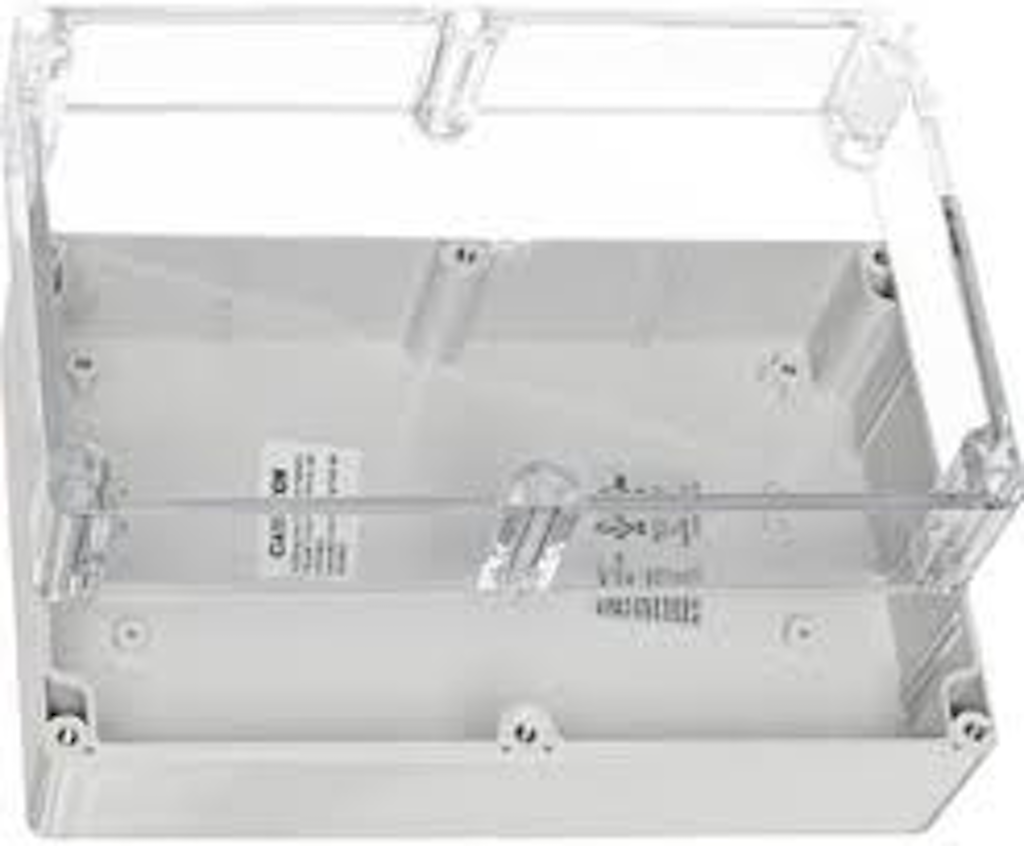
Figure 3.2: The Bud Industries PN-1325-C polycarbonate enclosure box.
3.2 Power Inputs [top]
On shore, the Pablo unit should be powered by a wall plug. On the vehicle, voltage might be supplied from the host or a companion battery. While it is technically possible to embed a battery within the enclosure, doing so increases system complexity by requiring custom circuitry to address recharging and use of wall power. Waterproof power connectors exist that provide a common DC barrel connector. The simplest solution is to expose this connector on a pigtail cable. On shore the connection receives a wall plug and on the vessel a short custom battery cable fits the connector.
3.2.1 Power requirements [top]
The computer is the main consumer of power on a Pablo unit. Selecting the minimum hardware that meets the software requirements makes sense as increased processor abilities translates directly to higher power consumption. If a more powerful computer is selected, it is possible (with size and weight limitations) to increase the battery. However, more power means additional waste heat in the sealed enclosure.
Voltage varies among computers but is commonly 5v (e.g., Raspberry Pi) or 12v (e.g., Portwell Nano-6060). Computers based on laptop systems sometimes demand 19v. Most 12-19v devices accept a range (e.g., 10.5v to 14.0v rather than just 12v), which is within the supply duty range of many battery packs. For example, a 14.4v source may start at 14.8v fully charged and drop to 13.0v before being taken out of service, all within the allowable input range of the motherboard. However, devices rated for 5v typically are more strict, specifying regulated power to between 4.5v and 5.5v. Therefore, 5v systems require a regulator while
3.2.2 Voltage regulators [top]
Regulators are devices that produce a constant output throughout a stated input range. There are three main types of regulators:
- Buck converters reduce voltage to the desired output and will often accept inputs right down to an equal pass-through.
- Boost converters increase the voltage to the desired output.
- Buck-boost converters provided a regulated voltage output from an input that can swing above or below the intended output.
Buck converters will stop producing a load on the power source once voltage drops below the defined threshold. Boost and buck-boost converters, however, will continue to draw power and may not cut off until the source can provide no additional current. This will draw down most batteries beyond repair so it is important to select a regulator that will cut off before damage occurs.
There are two types of voltage-reduction regulators (buck converters):
- Linear devices reduce voltage by shedding extra power as heat. They are simple and low-cost to implement, provide a clean output, but are inefficient and require a heat sink. An example is the LM7805, which produces a 5v output.
- Switch-mode regulators are highly efficient because they rely on a duty-cycle rather than generating heat. Because of complexity they are more expensive and more prone to fail. Also, the switching circuits can produce high-frequency waveforms that interfere with the systems receiving power.
The Pablo unit computer selection requires 5v and therefore a regulator is required. The Sino LLC 5V 3A 15W Step Down Regulator is a linear buck converter and was selected for its waterproofing, easily-accessed terminals, and stable 5v output.
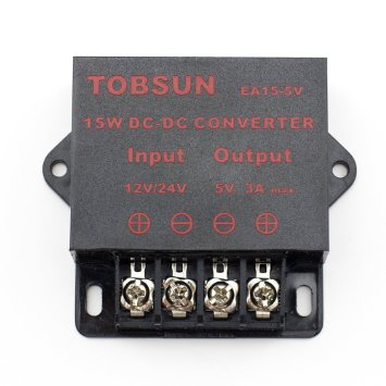
Figure 3.3: The Sino LLC 5V 3A 15W Step Down Regulator.
For the AC adapter, any plug-in "wall-wart" power supply with the following specifications is compatible with the Pablo unit: 5.5mm OD, 2.1mm ID positive tip connector
- 5.5mm x 2.1mm center-positive connector
- 5v with 2A (2000mAh) output current
- Input AC matching your locale (e.g., 110v in the U.S.)
3.3 Computing [top]
Specific requirements for Pablo computing include:
- Operating system. A GNU/Linux variant is required to support the autonomy system.
- MOOS-IvP and user code. Processing power must be sufficient to build MOOS-Ivp and user modules onboard the computer. Missions must be able to execute onboard without using full CPU.
- Footprint. Smaller size to fit within the enclosure.
- Peripheral connections. At least one Ethernet connector to interface with the front-seat; at least one and preferably two USB ports for user-supplied peripherals.
- Low power and cooling. Reduced power consumption translates to lower operating temperatures; the computer must be able to operate without active cooling inside the enclosure.
Recent advancements in mobile processing have increased the number of available computing options. Systems that fit within the baseline Pablo design include several small packaged systems such as the Intel NUC and various single-board computers like the Raspberry PI or BeagleBone Black. Generally, these devices are based on mobile processors, such as the Intel ATOM line or ARM chips.
3.3.1 Size Requirements [top]
The main selection criterion for computing is physical size; will the unit and associated peripherals fit inside the waterproof enclosure? The interior volume must contain the computer (some of which require an additional heat sink), the inward portion of panel receptacles, and space for wires and their connectors (a typical USB connector extends three centimeters from the receptacle). In addition, a Pablo unit may contain an optional display within the enclosure.
The waterproof housing selected for Pablo is approximately 8 in (20 cm) x 5 in (13 cm) x 1.75 in (4.4 cm). Interior space is impeded by risers along the enclosure's sides. Computers that fit within these dimensions include the Raspberry Pi, BeagleBone Black, and Gumstix computers. Surprisingly, a micro-ITX motherboard can fit inside the enclosure, provided that the the unit's peripheral ports are only along one side. The 1.9Ghz quad-core Portwell Nano-6060 is an example of a powerful single-board micro-ITX computer that can be arranged to fit in the box.
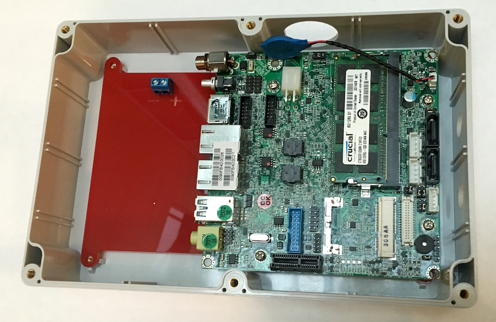
Figure 3.4: The Portwell Nano-6060 single-board computer fits tightly within the waterproof housing and is one possible computing option.
3.3.2 Computing Platform Selection and Alternatives [top]
Many platforms exist that provide sufficient computing resources and fit within the PABLO size and power budgets. As of this writing (fall 2015), the baseline PABLO unit is assembled using Raspberry Pi 2 Model B as its baseline computer. The Raspi was selected because it is small, inexpensive, low-power, and has a large community of supporters that provide answers for technical issues. The downside of the Raspi is the fixed RAM and the need for an off-board compilation toolchain.
All of the platforms that were considered meet the requirement of being able to run a baseline MOOS-IvP mission. The short list of computing options listed here provides a range of features that can be considered for Payload Autonomy applications:
- Raspberry Pi 2 Model B The smallest, least-expensive, and lowest-power option in our list. Huge support community and large number of purpose-built "shields" that extend hardware functionality. Onboard compiling can take many hours and requires memory-management tricks.
- BeagleBone Black Similar or slightly better than the Raspi on almost every metric except cost. Compared with the Raspi, community support and ease of availability are lacking. The BeagleBone also benefits from an off-board compiling toolchain.
- Micro-ITX Portwell Nano-6060 Many options exist in the Micro-ITX form factor. The Nano-6060 is a \textdollar 300 board with a quad-core 2.2Ghz ATOM processor. The unit is a tight fit in the PABLO enclosure but peripheral connections are all on the same side of the board to facilitate wiring. Power consumption is around 8W, which increases hotel load and may require temperature regulation.
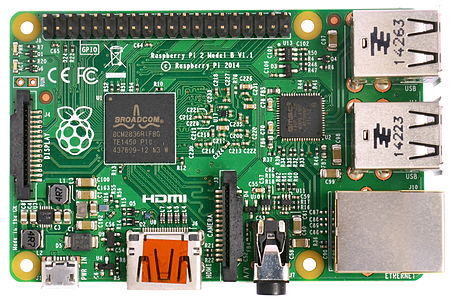
Figure 3.5: The Raspberry PI 2 Model B.
3.3.3 Connectors [top]
Pablo unit requirements call for four outside connections:
- 1 x Ethernet. Physical network interface to the host vehicle.
- 1 x Power. Two-conductor cable for input voltage.
- 2 x USB. Connect with user-supplied peripherals and to keyboard/mouse for non-network interface. The USB ports may not be a requirement for all Pablo users. However, we recommend including at least one for convenience.
Each connection represents a breach in the enclosure and therefore a potential violation of the waterproofing. Glands and connectors were selected for this project because of their waterproof ratings. Care must be taken to install gaskets and o-rings properly to avoid potential leaking.
Waterproofing a hole in plastic is a challenge. Glues and epoxies will peel off. Chemical bonding (such as PVC cement) form a undesirable permanent bond and cases such as cyanoacrylate on acrylics require controlled temperatures to prevent cracking. Simply drilling a hole, pass a cable, then apply silicone sealant will result in leaks, either due to lack of adhesion or from mechanical separation. Therefore, the only robust method for preventing leaks is to mechanically compress a gasket or o-ring around the hole.
Cable glands. Passing a cable through an enclosure wall without leaks requires the use of a cable gland, sometimes called "cord grips". The gland is a cylindrical body that is clamped to a hole in the enclosure. At one end of the gland body is a rubber sheath with a cinch nut that forms a waterproof seal with the cable jacket by compressing the rubber sheath.
When an existing, terminated cable is being used, glands pose a challenge because often the cable ends will not pass through the gland body. Some alternatives exist for sealing a terminated cable into a gland, however these often require similar levels of effort to cutting then manually terminating the cable, while increasing potential for leaks.
The two main considerations in selecting a gland are the outer diameter (OD) for the enclosure hole and the inner diameter (ID) that clasps the cable. Glands are sized using the historical "PG" standard. The number in the size description describes the maximum cable diameter in millimeters. The two sizes most relevant to the Pablo unit are:
| PG Name | Hole Diameter | Cable Diameter |
| PG7 | 0.492 in. (12.5 mm) | 0.118 to 0.256 in. (3.0 mm to 6.5 mm) |
| PG9 | 0.610 in. (15.5 mm) | 0.157 to 0.315 in. (4.0 mm to 8.0 mm) |
3.3.4 Gland selection [top]
Power and Ethernet enter the box through glands. The diameter of both cables meets the ID specification for the PG7 gland. These are common, widely-available parts often sold without markings and in bulk. However, we recommend the Bud Industries NG-9511 gland because it is from a known, reliable manufacturer, includes a datasheet with specifications, and has a gasket. If using a different version of the PG7 gland, always insert a gasket or o-ring between the gland's non-rotating portion and the box.
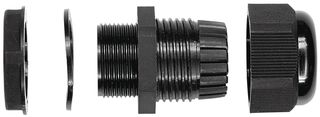
Figure 3.6: Exploded view of the Bud Industries NG-9511 PG7 Cable Gland.
USB Connectors. Multiple options exist for waterproof panel-mount USB connectors. The Bulgin Buccaneer series was selected as the best combination of price for reliability. The PX0842 exposes a USB-A receptable to the outside and a USB-B facing inward. When not in use, the PX0733 sealing cap retains the waterproofing. Inside Pablo, a short USB A-B cable connects the computer port and connector. Conveniently, any USB-A device can be plugged in when waterproofing is not required (such as a temporary-use keyboard). When field-deployed, waterproofing for the USB connections is maintained by splicing on a mating Buccaneer connector.
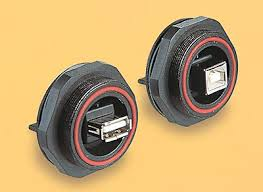
Figure 3.7: Bulgin Buccaneer waterproof USB connectors.
3.4 Interior Mounting [top]
A mounting plate inside the Pablo unit is needed in order to prevent impact damage to the computer and to reduce mechanical strain on cables. The selected enclosure includes mounting bosses which do not align with holes in the selected computer board. The solution is a custom mounting plate for the computer that bolts down to the enclosure bosses. Such a plate can be manually crafted, laser-cut, or purchased from an online service. The Bill of Materials section describes these options in detail.
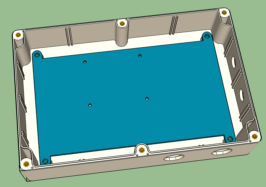
Figure 3.8: Drawing of the custom mounting plate positioned inside the Pablo enclosure.
4 Network Topology
When using MOOS, intra-community occurs over an IP network. Entire books are written to describe methods for managing packets over IP. Presented here is an overview that attempts to summarize the most relevant and important details. In continuing with MOOS standards, only IPv4 nomenclature is considered.
The Network Topology section provides background and is not required reading for configuring a PABLO box.
4.1 Network Topology Overview [top]
Each computer on a network has at least one IP node, a connection between the operating system on the computer and a network. It is possible to have more than one node, for example a physical node to an Ethernet port, a wireless connection, and an internal logical interface to a virtual machine. Each node is named with at least one IPv4 address, a collection of four numbers, each in the range 0-255. An example IP address is 192.168.1.100.
Moving from left to right, IP address numbers denote top level to local networks. Addresses starting with 192.168.x.x, 10.x.x.x, and combinations in the 172.x.x.x space represent private networks where the IP address is not directly visible to the open internet.
A subnet is a collection of nodes that share a common routing and therefore are all visible to one another. The simplest subnet uses the third number to define the subnet while the fourth describes a unique ID for each node. In this scenario, the 192.168.1.x subnet has space for 255 devices to connect.
One of the nodes on a subnet must be a router, which manages traffic between devices and acts as a gateway to send and receive data to a parent network (typically the internet). The router has a node that faces the wide area network (WAN) with single IP address. One or more connections inside the local area network (LAN), sometimes extended with a network hub or switch, facilitates connection of many local devices. When any of the devices on the LAN communicates out to the internet, it broadcasts the router's IP address.
Note that one or more of the devices in the subnet might itself be a router with a private network behind it. Using special tables, routers can be told how packets should be distributed within its private domain. For example, a router with the address 192.168.7.1 manages the private 192.168.7.x domain. Its outward-facing node is 192.168.1.151 and participates in the 192.168.1.x network. The router managing that network is told that packets destined for 192.168.7.x should be handed to 192.168.1.151. Now any node in the 192.168.1.x network can originate a packet destined for an address in the 192.168.7.x private network.
4.1.1 MOOS Simulations and the IP Network [top]
Network topology when running a MOOS simulation provides a starting point for describing payload autonomy network enhancements. The laptop typically used as the shoreside computer is connected to the primary network router and assigned a static IP address of 192.168.1.150.
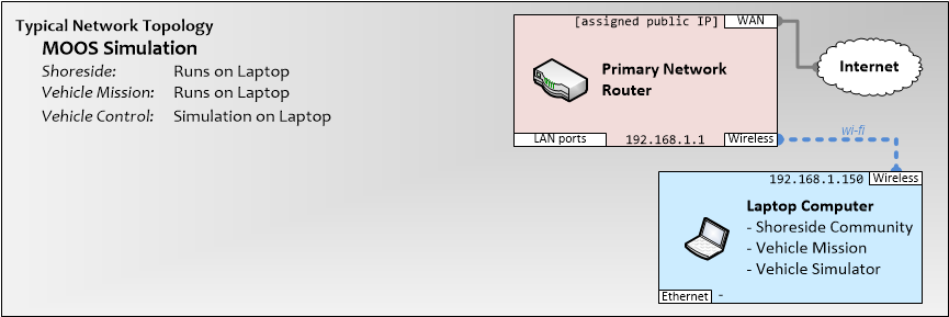
Figure 4.1: Network topology of a MOOS simulation with the shoreside computer connected to the primary network router.
4.1.2 Network Topology Without Payload Autonomy [top]
Systems running MOOS must be deployed on an IP-based LAN by definition. Vehicles and shoreside require network visibility. To reduce complexity, the typical arrangement is to attach cooperating MOOS nodes to the same subnet. For example, at MIT a common network layout is:
| Address | Node Description |
| 192.168.1.1 | Primary Router |
| 192.168.1.2 | Pass-through wireless access point |
| 192.168.1.150 | Shoreside computer |
| 192.168.1.171 | Vehicle A wireless radio / frontseat computer |
| 192.168.1.172 | Vehicle B wireless radio / frontseat computer |
| 192.168.1.n | Additional vehicle frontseat computers |
With a common subnet, the shoreside and both field units can all reach each other over the IP network using pShare. This topology is common in IvP simulation. For example, running the moos-ivp/ivp/missions/m4_dingo mission launches four simulated vehicles and a shoreside on the same computer. Each of these nodes happens to have the localhost address and therefore are all on the same subnet. (With localhost, traffic does not leave the network interface and is routed back into the originating computer.).
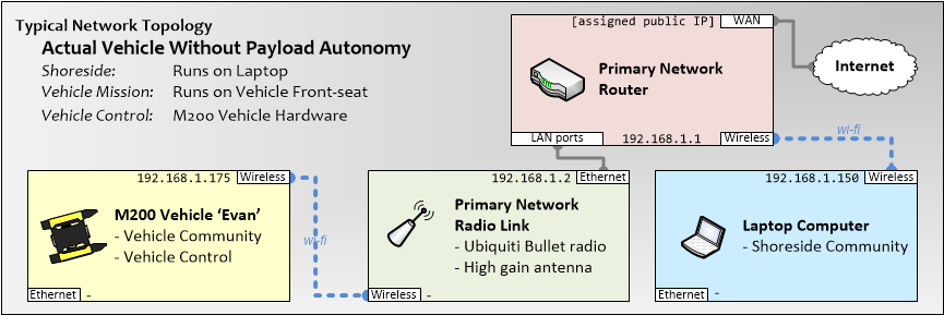
Figure 4.2: Network topology of a vehicle running MOOS on its frontseat.
4.1.3 Network Topology for Payload Autonomy [top]
In many cases there is no reason for the front seat to participate in the IP network. An example is the MIT 2014 RobotX vessel. The front seat on the WAM-V boat was implemented on an Arduino. That device manages vehicle actuation in consideration of MOOS inputs, system health, manual control, and the emergency-stop. It does not connect to the IP network or need access to the internet. In this and similar cases, the back-seat computer is directly connected to the IP network radio and therefore is itself a node on the common subnet.
Vehicles such as the Clearpath Kingfisher M200 provide a more complex arrangement where the front-seat computer manages the network hardware and the back-seat connects through a payload interface. Networking rules prohibit direct piggybacking; the back-seat cannot operate in the same subnet as the front-seat upstream connection. The solution is to create a separate subnet with the front-seat acting as the router. An IP address on the new subnet is assigned to the back-seat.
With the M200 as an example, the wireless radio is connected to the front-seat computer and gives it a node on the 192.168.1.x network. An Ethernet port in the payload bay is directly connected to and managed by the front-seat motherboard. As the router for an independent subnet, the front-seat assigns an IP address of 192.168.2.1 (note the .2. grouping) to the payload Ethernet port. Any device connecting to this node must be on the 192.168.2.x subnet for IP access to the front seat.
Conveniently, the 192.168.2.x subnet can reach out to the 192.168.1.x network by configuring simple routing settings on the M200 and by telling the primary router that the 192.168.2.x is reached by routing packets to the 192.168.1.x front-seat IP address. The following is an example of the network topology at MIT for implementing Pablo units with M200 vehicles:
| Address | Node Description |
| 192.168.1.1 | Primary Router |
| 192.168.1.2 | Pass-through wireless access point |
| 192.168.1.150 | Shoreside computer |
| 192.168.1.171 | Vehicle A wireless radio / front-seat computer |
| 192.168.2.1 | Vehicle A payload Ethernet port / front-seat computer |
| 192.168.2.100 | Pablo unit for vehicle A |
| 192.168.1.172 | Vehicle B wireless radio / front-seat computer |
| 192.168.3.1 | Vehicle B payload Ethernet port / front-seat computer |
| 192.168.3.100 | Pablo unit for vehicle B |
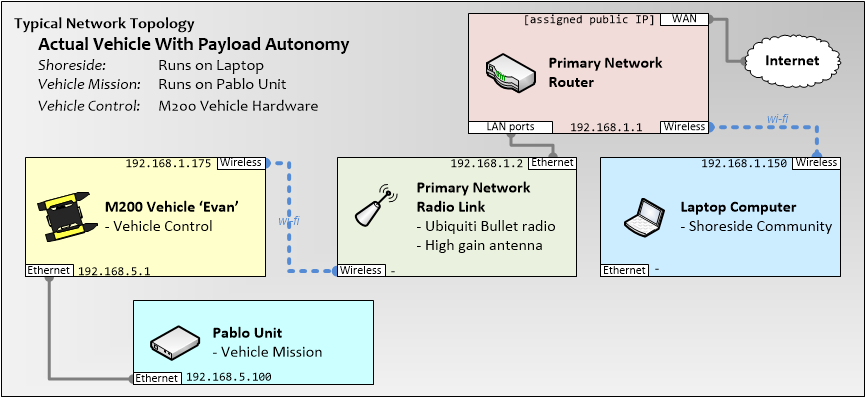
Figure 4.3: Network topology of a vehicle hosting a Pablo unit as the back-seat on a private subnet.
DHCP. One feature of the Pablo unit is that it can be readily attached to any actual or emulated vehicle without reconfiguring any system settings. This is achieved using a dynamic IP assignment protocol called DHCP. Instead of retaining a manually-assigned addres, each Pablo unit is configured that on starting up it polls its network hosts and asks for connection details. The front-seat is acting as a DHCP server and is prepared to answer connection requests.
Subnet Conventions. The MIT fleet has a number of M200 vehicles, named alphabetically (Archie, Betty, etc.). On the primary 192.168.1.x network, IP addresses start at 192.168.1.171 and increment respectively to the vehicle names. For example, it is readily obvious that the Evan vehicle is 192.168.1.175. The onboard subnets follow the same pattern, for example Evan hosts 192.168.5.171 (Archie has been retired and therefore does not conflict with the 192.168.1.x primary subnet).
Because there is only one payload Ethernet port, the private subnet on each vehicle can only support one client. The convention at MIT is to assign .100 as the node address. Therefore, a Pablo unit can always be reached at the address 192.168.XXX.100, where XXX is the vehicle's numerical letter equivalent.
4.1.4 Network Topology for Vehicle Emulation with Payload Autonomy [top]
A powerful aspect of the Pablo unit is the ability to connect with an emulated vehicle or actual hardware without reconfiguring the system. In this arrangement, the emulated vehicle runs on the same computer that is running as shoreside. The Pablo unit connects to the Ethernet port on the laptop, which is configured with a private subnet. This arrangement also conveniently shares internet access from the wifi connection to the Pablo.
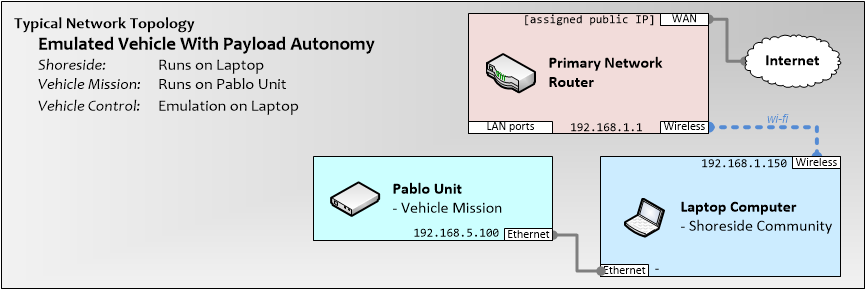
Figure 4.4: Network topology of Pablo unit acting as the back-seat to an emulated front-seat on shoreside.
5 Network Configuration
This section describes how to set up the shore, Pablo units, and Kingfisher M200 autonomous surface vehicles in a payload autonomy configuration. This setup can be extended to similar arrangements where the vehicle front-seat acts as a pass-through network for the back-seat.
- Router. Standard-office-home-office (SOHO) router, preferably with wifi, to manage the primary network. Examples here use a Linksys EA6500 but the principles should transfer to other devices that expose access to advanced routing parameters.
- Computer. A laptop or desktop computer with a wireless card and Ethernet port. Examples here refer to this computer as the laptop.
- Wireless Access Point. A radio unit that talks to deployed vehicles. Wifi on the router may not have range to reach field nodes. The M200 vessels are compatible with Ubquiti Networks radios and examples here describe setup for the Ubiquiti Bullet.
5.1 Initial Primary Router Configuration [top]
The objective of this step is to configure the router to manage the 192.168.1.x network. For most routers, the general steps are as follows:
- Initialize. Reset the router to factory settings (not necessary with a new device).
- WAN Settings. Per the manufacturer's instructions, configure the device for an internet connection.
- LAN Settings. Configure the local area network so that the router has IP 192.168.1.1 and that DHCP addresses start at 192.168.1.200.
- Manual Addresses. Assign fixed IPs to known computers, specifically 192.168.1.150 to the primary computer used for shoreside.
- Wireless Settings. Configure the wifi with an SSID name and password. Changes on each page require applying settings which will cause a reboot and temporary lack of access to the device. NOTE, When changing the Bullet IP address on the Networking page, use the new address to connect with the Bullet.
- Wiress Settings Verification. When all settings have been set, return to all tabs to verify settings. It is possible for settings to reset items on other tabs.
- Laptop Setup. On the laptop, configure wireless settings to connect via DHCP to the network SSID.
Verification. Verify that the laptop connects to the network and receives the 192.168.1.150 address. Once connected, verify that the internet is accessible from the laptop.
5.2 Field Wireless Radio Configuration [top]
The Ubiquiti Networks Bullet (all variants) is known to connect with the M200 wireless radio. The Bullet has one Ethernet port that connects directly to the primary router and is configured into WDS mode, which provides a transparent hop on the subnet. Any vehicle that connects to the Bullet appears connected to the primary router as if by Ethernet cable.
To configure a Bullet radio:
- Provide 24v Power Over Ethernet. Use the black box near the door of the lab. Connect the Bullet to configure to the LAN port and your laptop to the WAN port.
- Bullet Reset. Plug in the black box to power on the Bullet. After one minute, press and hold the reset button for 10 seconds. (The button is adjacent to the ethernet port; a Bic pen cap works well for this.) Wait one minute for the reset to complete.
- Laptop Setup. Turn off wifi on the laptop. Configure the ethernet port as follows: IP address = 192.168.1.151; Subnet Mask = 255.255.255.0; Router = (blank).
- Connect with the Bullet. Open a browser and enter http://192.168.1.20. The login is ubnt/ubnt.
- Bullet Settings. Configure or verify settings per the table below.
- Laptop Setup. Return the laptop ethernet settings to their original values and turn the wifi back on.
- Verification. Return the cable configurations so that the Bullet is connected into the lab main router. Verify that field Bullets can connect to the lab network via the newly configured Bullet.
| Ubiquiti Tab | ||
| Subcategory | Setting Description | Value |
| airMAX Settings | airMAX | (not enabled) |
| Long Range PtP Link Mode | (not enabled) | |
| airView | airView Port | 18888 |
| airSelect | airSelect | (not enabled) |
| Main Tab | ||
| Subcategory | Setting Description | Value |
| (No settings to change) |
| Wireless Tab, Basic Wireless Settings | ||
| Subcategory | Setting Description | Value |
| Basic Wireless Settings | Wireless Mode | Access Point |
| WDS | Enable | |
| SSID | [user choice] | |
| Country Code | [user choice] | |
| IEEE 802.11 Mode | B/G/N mixed | |
| Channel Width | 20 Mhz | |
| Channel Shifting | Disable | |
| Frequency, MHz | Auto | |
| Extension Channel | None | |
| Frequency List, MHz | (not enabled) | |
| Auto Adjust to EIRP Limit | (not enabled) | |
| Antenna Gain | 0 dBi | |
| Cable Loss | 0 dB | |
| Output Power | 28 dBm | |
| Data Rate Module | Default | |
| Max TX Rate, Mbps | MCS 7 - 65 Automatic |
Selection for wireless security type is left up to the user. This documentation describes setting up WEP, which is considered a vulnerable protocol. It is used here simply as a low-overhead method to prevent access of opportunity, not to provide an impregnable network. If your requirements dictate increased security, replace the described WEP details with WPA2 settings.
| Wireless Tab, Wireless Security | ||
| Subcategory | Setting Description | Value |
| Wireless Security | Security | WEP |
| Authentication Type | Open | |
| WEP Key Length | 128 bit | |
| Key Type | ASCII | |
| WEP Key | [user choice] | |
| Key Index | 1 | |
| MAC ACL | (not enabled) |
| Network Tab | ||
| Subcategory | Setting Description | Value |
| Network Role | Network Mode | Bridge |
| Disable Network | None | |
| Configuration Mode | Configuration Mode | Simple |
| Management Network Settings | Management IP Address | Static |
| IP Address | 192.168.1.2 | |
| Netmask | 255.255.255.0 | |
| Gateway IP | 192.168.1.1 | |
| Primary DNS IP | 8.8.8.8 | |
| Secondary DNS IP | 192.168.1.1 | |
| MTU | 1500 | |
| Management VLAN | (not enabled) | |
| Auto IP Aliasing | (not enabled) | |
| STP | (not enabled) |
| Advanced Tab | ||
| Subcategory | Setting Description | Value |
| Advanced Wireless Settings | RTS Threshold | 2346 Off |
| Distance | .4 miles Auto Adjust On | |
| Aggregation | 32 Frames 50000 Bytes Enabled | |
| Multicast Data | Allow All | |
| Multicast Enhancement | Enable | |
| Installer EIRP Control | Enable | |
| Extra Reporting | Enable | |
| Client Isolation | (not enabled) | |
| Sensitivity Threshold, dBm | -96 Off | |
| Advanced Ethernet Settings | Lan0 Speed | Auto |
| Signal LED Thresholds | LED1 | 94 |
| LED2 | 80 | |
| LED3 | 72 | |
| LED4 | 65 |
| Services Tab | ||
| Subcategory | Setting Description | Value |
| Ping Watchdog | Ping Watchdog | (not enabled) |
| SNMP Agent | SNMP Agent | (not enabled) |
| Web Server | Web Server | Enable |
| Secure Connection (HTTPS) | (not enabled) | |
| Secure Server Port | 443 | |
| Server Port | 80 | |
| Session Timeout | 15 minutes | |
| SSH Server | SSH Server | Enable |
| Server Port | 22 | |
| Password Authentication | Enable | |
| Authorized Keys | (edit list should be empty) | |
| Telnet Server | Telner Server | (not enabled) |
| NTP Client | NTP Client | (not enabled) |
| Dynamic DNS | Dynamic DNS | (not enabled) |
| System Log | System Log | (not enabled) |
| Remote Log | (not enabled) | |
| Device Discovery | Discovery | Enable |
| CDP | Enable |
5.3 M200 Vehicle Network Configuration [top]
WARNING: The instructions provided here require modifying the M200 front-seat from the manufacturer's settings. Terminal access to the computer is achieved via the payload Ethernet port. It is possible that altering parameters may disable network access. Repairing this situation requires opening the computing bay and connecting a keyboard and screen directly to the front-seat.
Prequisites:
- M200 Vehicle. Instructions here assume that the M200 has original network parameters as provided by the manufacturer.
- Primary Router. The primary router must be at its initial configuration as described above.
- Field Wireless Radio. The wifi radio used for field connectivity must be connected as described above.
- Laptop. Computer with access to Ethernet and wireless settings.
M200 initial login. As delivered from the manufacturer, the M200 allows a laptop to connect with the front-seat computer through the payload bay Ethernet connector:
- With the M200 turned off, connect an Ethernet cable between the payload port of the M200 and a laptop.
- Configure the laptop to have an IP address of 192.168.1.10 and subnet mask of 255.255.255.0. Other network options should be cleared.
- Turn off the wifi or other network connections on the laptop.
- Power on the M200.
- After a couple of minutes, use $ ping 192.168.1.1 to verify that the front seat is booted and ready.
- Connect to the front seat using the default login: $ ssh administrator@192.168.1.1 (password clearpath).
M200 Network Configuration. M200 network connection details are configured in the /etc/network/interfaces file. This file must be edited so that the M200 can connect to the primary network. To support a Pablo unit connected to the payload connector, the M200 also must serve as a DHCP router, always giving the attached Pablo unit an IP address 192.168.YYY.100, where YYY is the vehicle's private subnet number. Once the primary router is set up and the M200 initial login is complete, these steps allow the M200 to connect with the wireless router:
- Create a backup of the existing network configuration:
$ sudo cp /etc/network/interfaces /etc/network/interfaces.backup
- Using sudo and your favorite editor, open the original file. For example, using vi the file can be opened as follows:
$ vi /etc/network/interfaces
- Determine the rightmost number for the address per your IP numbering scheme, it will replace the XXX in the configuration listing below.
- Determine the subnet number for the address of the payload bay private network on the M200. That number will replace YYY in the configuration listing below.
- Identify the password for your wireless network security ro replace ZZZ in the configuration listing below. If using a security scheme besides WEP, it may be necessary to replace or add wireless lines in the listing.
- Edit the file to have the following contents. Replace XXX with your choice of IP address. Replace YYY with your network's WEP password or replace relevant wireless lines to match another security scheme:
etc/network/interfaces}
 auto lo
 iface lo inet loopback
 auto wlan0
 iface wlan0 inet static
 address 192.168.1.XXX
 netmask 255.255.255.0
 gateway 192.168.1.1
 dns-nameservers 8.8.8.8 8.8.4.4
 wireless-essid ubnt
 wireless-mode  Managed
 wireless-key1 s:[ZZZ]
 wireless-keymode open
 auto eth0
 iface eth0 inet static
 address 192.168.YYY.1
 netmask 255.255.255.0
 broadcast 192.168.6.255
- Commit the file changes and close the editor.
- Reboot the M200 vehicle and verify that it is connected to the wireless network by pinging its IP address from your laptop:
$ ping 192.168.1.XXX
- Log back into the M200 vehicle and verify that it has internet access:
$ ping mit.edu
- Install the dhcp service:
$ sudo apt-get install isc-dhcp-server
- The file /etc/dhcp/dhcpd.conf defines dhcp server settings. Using sudo and your favorite editor, modify the following file contents (remember to replace YYY with the vehicle's subnet ID):
 ddns-update-style none;
 subnet 192.168.YYY.0 netmask 255.255.255.0
 {
 range                      192.168.YYY.100 192.168.YYY.100;
 option routers             192.168.YYY.1;
 option subnet-mask         255.255.255.0;
 option domain-name-servers 192.168.1.1;
 option broadcast-address   192.168.YYY.255;
 default-lease-time         1;
 max-lease-time             2;
 }
- In the same file, uncomment the line:
authorit ative;
- Commit the file changes an d close the editor.
- To tell the DHCP service which interface to use, use sudo and your favorite editor to edit the INTERFACES line in the file /etc/default/isc-dhcp-server:
INTERFACES="eth0"
- Enable packet forwarding between the wireless and wired networks; with sudo and your preferred editor, open /etc/sysctl.conf and edit the line as follows:
net.ipv4.ip_forward=1
- With the configuration files edited, the dhcp service can be restarted:
 $ sudo service isc-dhcp-server restart
 $ sudo service isc-dhcp-server start
 $ sudo service isc-dhcp-server stop
Listing 5.1 - .
5.3.1 PABLO Network Configuration [top]
The Pablo's computer is configured to accept a dynamic address through a DHCP connection and a fixed IP over the same Ethernet port to be used for troubleshooting. This step is easiest if attempted with a keyboard and display connected directly to the computer prior to installation in the enclosure.
M200 network connection details are configured in the /etc/network/interfaces file. Once the primary router is set up and the M200 initial login is complete, these steps allow the M200 to connect with the wireless router:
- After logging onto the computer, create a backup of the existing network configuration:
$ sudo cp /etc/network/interfaces /etc/network/interfaces.backup
- Using sudo and your favorite editor, open the original file. For example, using vi the file can be opened as follows:
$ vi /etc/network/interfaces
- Edit the file to have the following contents, which are the same for all Pablo units:
etc/network/interfaces}
 auto lo
 iface lo inet loopback
 iface eth0 inet dhcp
 auto eth0:1
 iface eth0:1 inet static
 address 192.168.254.100
 netmask 255.255.255.0
 dns-nameservers 8.8.8.8 8.8.4.4
- Commit the file changes and close the editor.
- With an Ethernet cable, connect the Pablo computer to the M200 payload port.
- From your laptop, log into the front-seat computer on the M200:
$ ssh [user]@192.168.1.XXX
- Reboot the Pablo computer and verify that it is connected to the M200 private subnet and received the proper DHCP address. From the M200 front-seat computer:
$ ping 192.168.YYY.100
Listing 5.2 - .
5.3.2 Additional Primary Router Configuration [top]
In the prior section, verification was completed from the M200 front-seat and not from a laptop connected to the primary network. The reason for this is that while the M200 is configured to route packets into the Pablo, the primary router does not yet know of the existance of any subnets and therefore throws away any packets destined for M200 payload ports. These additonal configurations are needed on the primary router:
- Log into the primary router as the administrator.
- Navigate to the advanced routing settings page. On Linksys routers this is reached by clicking the Connectivity button on the main page then selecting the Advanced Routing tab along the top.
- The objective is to create a static route to the vehicle subnets through the vehicle's primary network addresses. On the Linksys this is done by clicking the Add Static Route button. Create a new static route for each vehicle in your fleet with the following settings:
- Each route is named. The MIT convention is use the label payload[vehicle name[ (e.g., payloadEvan).
- The destination IP is 192.168.XXX.0, where XXX is the subnet number for each vehicle (e.g., Evan's desination ID is 192.168.5.0).
- The subnet mask is always 255.255.255.0.
- The gateway is the IP address of the vehicle's front seat on the primary network (e.g., Evan's gateway is 192.168.1.175).
- The interface is LAN.
- Disconnect from the router then reboot it to ensure all settings are applied.
- Verify the settings for each vehicle by connecting a Pablo unit and attempting to ssh or ping to the unit from a laptop connected to the primary network.
5.4 Pablo Computer Preparation [top]
A new Raspi arrives in a box and the user must install the SD card and the embedded display. Before preparing the Raspi, prepare the SD card as described in Section ???, above. Inserting the SD card is straightforward.
5.4.1 Raspi TFT Display - Software Configuration and Hardware Setup [top]

Figure 5.1: \bf The Adafruit PiTFT Plus 320x240 2.8" TFT installed in a PABLO unit.
It is useful to have a display connected to the Raspi for setup and occasionally during use. Historical versions of the Pablo box included an external HDMI connector that was deprecated due to lack of adequate waterproofing. Currently, connecting a display requires unscrewing the lid and using the Raspi's onboard HDMI port.
Several models of small thin-film-transistor (TFT) liquid-crystal display (LCD) units are available for the Raspi. We recommend the PiTFT Plus 320x240 2.8" TFT, produced by Adafruit Industries, LLC (Adafruit), who also maintains code for related interface drivers. The display includes an integrated touchscreen, which is not convered by our instructions (it is not useful behind the Pablo's cover). The official web site is here:
https://www.adafruit.com/products/2298
When installed and configured, the Adafruit TFT replaces output destined for the HDMI port. As the Raspi powers on, the splash screen and initial boot messages are sent out the HDMI port. Midway through the boot process, the display drivers load and console output is diverted to the TFT screen. The screen is small but still usable for troubleshooting to revive an ssh connection. In general use, the TFT is used to display the IP address.
For convenience, the instructions listed here describe how to download pre-built binaries and how to configure the OS to use them. Following the instructions below suggests that you trust the binary packages being downloaded. It is possible to download source code and compile independently per directions on the adafruit website. In addition, the configuration step can be simplified using their helper script. Details are provided here in order to support some options not included in their scripts.
Step 1 - Modifying the Raspian Kernel. The operating system does not have native support for the display. Adafruit has packaged the drivers and makes them available from their wesbite.
Start by powering on the Raspi then logging in via ssh and updating all installed packages:
$ sudo apt-get update
The PiTFT packages drivers are available from the apt.adafruit.com server, which must be added to the list of available software sources: \\
$ curl -SLs https://apt.adafruit.com/add-pin | sudo bash
With the packages available, install the kernel that has PiTFT packages (this may take around 20 minutes on a Raspi Model 2):
$ sudo apt-get install raspberrypi-bootloader
Step 2 - Add the Device Tree Overlay. Raspbian uses the concept of the Device Tree (DT) to describe manageable hardware in the system. A full description of DTs is here: https://www.raspberrypi.org/documentation/configuration/device-tree.md The file /boot/config.txt contains DT details and must have several lines appended in order to recongnize the TFT unit (replace vi with your preferred text editor):
$ sudo vi /boot/config.txt
Listing 5.3 - . /boot/config.txt}
   [pi1]
   device_tree=bcm2708-rpi-b-plus.dtb
   [pi2]
   device_tree=bcm2709-rpi-2-b.dtb
   [all]
   dtparam=spi=on
   dtparam=i2c1=on
   dtparam=i2c_arm=on
   dtoverlay=pitft28r,rotate=270,speed=16000000,fps=10
The rotate, speed, and fps options can be edited at any time, reboot to commit changes.
- rotate: Describes which direction is the display top. 0 (portrait), top near SD card; 180 (portrait), top near ports; 90 (landscape), top toward HDMI port; 270 (portrait), top toward header.
- speed: Screen refresh rate. The slowest setting 16000000 is 16Mhz, which is more than acceptable for console work. If the display is used for graphics, 32000000 can be set instead.
- fps: Frames per second; 10 is acceptable for console text, 20 can be used to improve graphics output but will have a performance hit.
Shut down the Raspi to install the display (if already attached, a reboot is still required): \\
$ sudo shutdown -h 0
Step 3 - Installing the TFT Display. The Raspi must be configured to support an ssh connection before installing a display. The installation process will disable the HDMI display and it is inconvenient (but possible) to configure the Raspi on a tiny screen.Disconnect power from the Raspi. Assure proper grounding. The display board simply presses down onto the Raspi header pins. On the Model 2, where the Raspi includes additional pins, match with the header pins closest to the SD card.
At this point, rebooting will display a blank screen.
Step 4 - Directing Output to the Console. Following the steps above, the kernel is installed and the device tree is configured to support the TFT's framebuffer but the console does not yet get directed to the TFT. By default, text is pushed to the HDMI framebuffer at /dev/fb0. Now, we want output to be pushed to the new PiTFT framebuffer at /dev/fb1.
Power on the Raspi. The screen will begin all white then turn to all black indicating that it is powered but not receiving any data to display. Via ssh, edit the boot configuration file: \\
$ sudo vi /boot/cmdline.txt
Locate the line ending in rootwait. Add fbcon=map:10 fbcon=font:VGA8x8 consoleblank=0, ensuring that it appears on the same line. The entire file should appear as follows:
Listing 5.4 - Device Tree Overlay lines added to the end of /boot/config.txt.
      dwc_otg.lpm_enable=0 console=ttyAMA0,115200 console=tty1
      root=/dev/mmcblk0p2 rootfstype=ext4 elevator=deadline fsck.repair=yes
      rootwait fbcon=map:10 fbcon=font:VGA8x8 consoleblank=0
The consoleblank parameter indicates that the display shall not go to sleep during periods of inactivity. It is also necessary to edit the /etc/kbd/config file as in:
$ sudo emacs -nw /etc/kbd/config
Locate the BLANK_TIME parameter and set its value to 0.
Reboot the raspi to enjoy console text on the TFT display.
5.5 Pablo Assembly Instructions [top]
The PABLO reference design can be assembled almost entirely by an individual with novice mechanical skills. The exception is cutting holes for the waterproof connectors, which can be solved via other means, see below. After acquiring items listed in the bill of materials, the PABLO unit can be assembled following these steps:
- Raspi. Install TFT and microSD card into the Raspi.
- Enclosure Cut holes for waterproof connectors.
- Mounting Plate Attach Raspi to the mounting plate and instal the plate in the enclosure.
- Glands Route power and Ethernet cables through glands, attached connectors, and install in the enclosure.
- Wiring Attach USB, power, and Ethernet cables inside the enclosure.
- Test and Seal Test the system then attach the enclosure lid.
5.6 Enclosure Preparation [top]
Off-the-shelf, the Bud Industries PN-1325C provides NEMA4X (IP66) dust and water ingress protection. The box is sealed against all dust and is rated for protection against water jets. In practice the box is splash-proof and can be contained in a wet payload bay it may not survive being submersed. The major concern in preparing the enclosure is to retain the waterproofing. Suggested methods for cutting the holes include:
Professional machinist. The most ideal method for cutting holes in the polycarbonate PN-1325C enclosure is to retain the services of an individual who is experienced in working with flexible plastic boxes.
Laser Cutting. The enclosure is polycarbonate and can be cut in a laser cutting machine, provided the bed depth can contain the box. While this method can produce excellent results, it may require iterative testing to optimal ideal cutting parameters for the material.
Gland holes: mill or drill press.
Using a mill, the 0.5-inch holes for the glands can be cut using a 1/2-inch end mill. Using a drill press, the hole can be created using progressively larger bits to prevent binding and cracking. In both cases, care should be taken to rigidly anchor the box to prevent vibration and possibly to support the inside of the box to prevent bowing under pressure.
Gland holes: hand drill. The 0.5-inch holes for the glands can be cut using an electric drill with the box locked in a suitable vise but expect an imprecise position and an oblong hole. While progressively larger bit sizes will work, a cleaner hole can be achieved using a stepper bit.
USB holes: manual method - not recommended. Holes for the Bulgin connectors can be created by drilling a 1-inch hole with any of the aforementioned techniques. Note that this large of a hole is likely to result in cracking. Cutting the hole with the lid attached reduces the likelihood of box damage. Use a hand reamer to increase the size of the hole to fit the connector. A small hand file can be used to cut the key notch.
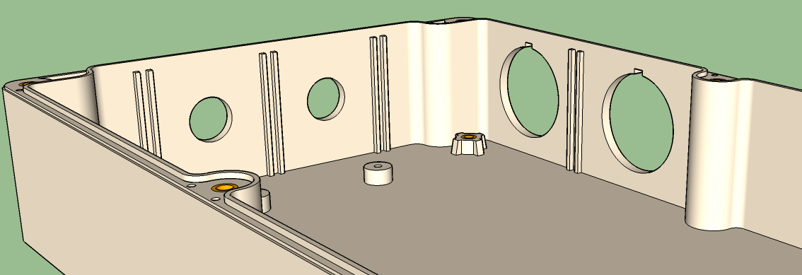
Figure 5.2: PABLO unit enclosure with holes cut for glands and USB connectors.
Precut Boxes [top]
Although availability is not guaranteed, MIT retains a collection of boxes that have precut holes. Contact our group at the general email address provided at http://www.moos-ivp.com.
The baseline PABLO unit design calls for four holes to be cut, as shown in Figure 5.2:
- Power wire gland
- Ethernet cable gland
- Bulgin Buccaneer USB connector 1
- Bulgin Buccaneer USB connector 2
Gland holes are located on a short side of the box. Each is a 0.5-inch diameter circle, centered in the panel space, as show in Figure 5.3:
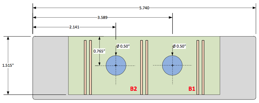
Figure 5.3: \bf Mechanical drawing describing PABLO unit holes for the glands.
Holes for the Bulgin Buccaneer USB connectors are located on a long side, adjacent to the side containing the glands (see Figure 5.2 for reference). Positions for the USB holes are show in Figure 5.4. Exact cutting dimensions are described in Figure 5.5.
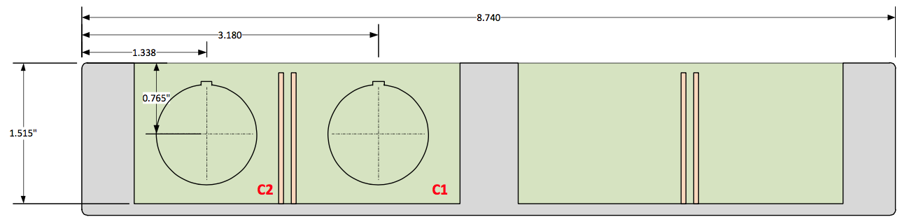
Figure 5.4: \bf Mechanical drawing describing PABLO unit holes for the USB connectors.
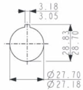
Figure 5.5: \bf Bulgin Buccaneer hole descriptions.
6 Mounting Plate
The mounting plate retains the Raspberry Pi inside the enclosure. Without the plate, there is no way to secure the Raspi inside the box. The plate can by downloading the design and laser cutting, machining, or manually sawing an acrylic plate. Alternatively, the plate can be ordered from Ponoko for a small creation and delivery fee. Plate thickness should be 3 or 4 mm.
Figure 6.1: \bf Mounting plate installed in the enclosure.
Accessing the Design File The mounting plate design file is an encapsulated postscript (EPS) file that is hosted at http://www.ponoko.com/showroom/MITPablo. The design is in the public domain and can be downloaded, modified, and used without restriction or attribution. The EPS file format can be loaded into most drawing software packages that are used with laser cutters.
Ordering a Completed Plate The company Ponoko offers services for cutting the file and delivering the part. The middle-sized (P2) sheet of acrylic is required to cut at least one plate but is large enough to cut several. If you are ordering more than one plate, modify the EPS file to include multiple copies of the design within the plate. Note that Ponoko charges for distance the laser travels so it is efficient to share cut edges as possible.
6.1 Installing the Raspi [top]
The Raspberry Pi is elevated above the mounting plate in order to avoid crushing bottom-mounted components and to improve access to peripheral connectors. M3 screws secure the computer to the plate with the hex nuts secured on the bottom of the plate.
Page built from LaTeX source using texwiki, developed at MIT. Errata to issues@moos-ivp.org. Get PDF