
- pMarineViewer
- uHelmScope
- Geometry Utilities
- uTimerScript
- pContactMgrV20
- uProcessWatch
- uLoadWatch
- pNodeReporter
- uXMS
- uSimMarineV22
- pMissionHash
- pMissionEval
- pHostInfo
- uPokeDB
- uQueryDB
- uMayFinish
- pEchoVar
- pDeadManPost
- pObstacleMgr
- iSay
- pRealm
- pSearchGrid
- pSpoofNode
- uTermCommand
- uSimCurrent
- uFldNodeBroker
- uFldShoreBroker
- uFldNodeComms
- uFldMessageHandler
- uFldBeaconRangeSensor
- uFldContactRangeSensor
- uFldCollisionDetect
- uFldCollObDetect
- uFldObstacleSim
- uFldScope
- uFldPathCheck
2.680 Competition Apps

uFldBeaconRangeSensor: Simulating Vehicle to Beacon Ranges
Maintained by: mikerb@mit.edu  Get PDF
1 Overview
2 The uFldBeaconRangeSensor Interface and Configuration Options
2.1 Configuration Parameters of uFldBeaconRangeSensor
3 Publications and Subscriptions for uFldBeaconRangeSensor
3.1 Variables Published by uFldBeaconRangeSensor
3.2 Variables Subscribed for by uFldBeaconRangeSensor
4 Using and Configuring uFldBeaconRangeSensor
4.1 Configuring the Beacon Locations and Properties
4.2 Unsolicited Beacon Range Reports
4.3 Solicited Beacon Range Reports
4.4 Limiting the Frequency of Vehicle Range Requests
4.5 Producing Range Measurements with Noise
5 Terminal and AppCast Output
6 Interaction between uFldBeaconRangeSensor and pMarineViewer
6.1 The VIEW_MARKER Data Structure
6.2 The VIEW_RANGE_PULSE Data Structure
7 The Indigo Example Mission Using uFldBeaconRangeSensor
7.1 Examining the Log Data from the Indigo Mission
7.2 Generating Range Report Data for Matlab
1 Overview
The uFldBeaconRangeSensor application is a tool for simulating an on-board sensor that provides a range measurement to a beacon where either (a) the vehicle knows its own position but is trying to determine the position of the beacon via a series of range measurements, or (b) the vehicle knows where the beacon(s) are but is trying to determine its own position based on the range measurements from one or more beacons at known locations.
The range-only sensor may be one that responds to a query, e.g., an acoustic ping, with an immediate reply, e.g. another acoustic ping or echo, from which the range from the the source to the beacon is determined by the time-of-flight of the message through the medium, e.g., the approxe speed ound through water. This idea is shown below on the left. Alternatively, if the beacon emits its message on a precise schedule with a clock precisely synchronized with the vehicle clock, the range measurement may be derived without requiring a separate query from the vehicle. This is the idea behind long baseline acoustic navigation, \cite{?,?,?,?} . This idea is shown below on the right.
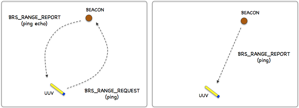
Figure 1.1: Beacon Range Sensors: A vehicle determines its range to a beacon by either (a) emitting a query and waiting for a reply, or (b) waiting for a message to be emitted on fixed schedule. In each case, the time-of-flight of the message through the medium is used to calculate the range.
In the uFldBeaconRangeSensor application, the beacon and vehicle locations are known to the simulator, and a tidy BRS_RANGE_REPORT message is sent to the vehicle(s) as a proxy to the actual range sensor and calculations that would otherwise reside on the vehicle. The MOOS app may be configured to have beacons provide a range report either (a) solicited with a range request, or (b) unsolicited. One may also configure the range at which a range request will be heard, and the range at which a range report will be heard. The app may be further configured to either (1) include the beacon location and ID, or (2) not include the beacon location or ID.
Typical Simulator Topology [top]
The typical module topology is shown in Figure 1.2 below. Multiple vehicles may be deployed in the field, each periodically communicating with a shoreside MOOS community running a single instance of uFldBeaconRangeSensor. Each vehicle regularly sends a node report noted by the simulator to keep an updated calculation of each vehicle to each simulated beacon. When a beacon wants to simulate a ping, or range request, it generates the BRS_RANGE_REQUEST message send to the shore. After the simulator calculates the range, a reply message, BRS_RANGE_REPORT is sent to the vehicle.
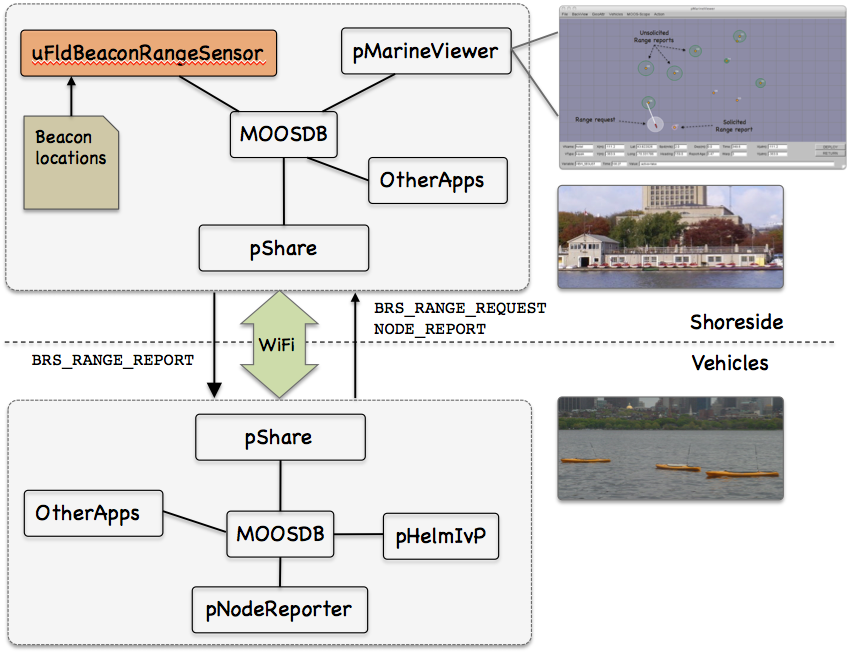
Figure 1.2: Typical uFldBeaconRangeSensor Topology: The simulator runs in a shoreside computer MOOS communicty and is configured with the beacon locations. Vehicles accessing the simulator periodically send node reports to the shoreside community. The simulator maintains a running estimate of the range between vehicles and beacons, modulo latency. A vehicle simulates a ping by sending a range request to shore and receiving a range report in return from the simulator.
If running a pure simulation (no deployed vehicles), both MOOS communities may simply be running on the same machine configured with distinct ports. The pShare application is shown here for communication between MOOS communities, but there are other alternatives for inter-community communication and the operation of uFldBeaconRangeSensor is not dependent on the manner of inter-communication communications.
2 The uFldBeaconRangeSensor Interface and Configuration Options
The uFldBeaconRangeSensor application may be configured with a configuration block within a .moos file. Its interface is defined by its publications and subscriptions for MOOS variables consumed and generated by other MOOS applications. An overview of the set of configuration options and interface is provided in this section.
2.1 Configuration Parameters of uFldBeaconRangeSensor [top]
The following parameters are defined for uFldBeaconRangeSensor. A more detailed description is provided in other parts of this section. Parameters having default values are indicated so.
Listing 2.1 - Configuration Parameters for uFldBeaconRangeSensor.
| beacon: | Description of beacon location and properties. Section 4.1. |
| default_beacon_freq: | Frequency of unsolicited beacon broadcasts ("never"). Section 4.2. |
| default_beacon_push_dist: | Range at which ... Section 4.1. |
| default_beacon_pull_dist: | Range at which ... Section 4.1. |
| default_beacon_width: | Width of beacons (meters) when rendered (4). Section 4.1. |
| default_beacon_color: | Color of beacons when rendered ("red"). Section 4.1. |
| default_beacon_shape: | Shape of beacons when rendered ("circle"). Section 4.1. |
| ground_truth: | If true, ground truth is also reported when noise is added. Section 4.5. |
| node_pull_dist: TBW Section 4.1. | |
| node_push_dist: TBW Section 4.1. | |
| ping_payments: | How pings treated w.r.t. ping wait time ("upon_response"). Section 4.4. |
| ping_wait: | Mandatory number of seconds between successive vehicle pings. Section 4.4. |
| report_vars: | Determines variable name(s) used for range report ("short"). |
| rn_algorithm: | Algorithm for adding random noise to range measurements. |
| verbose: | If true, verbose status message terminal output (false). |
An Example MOOS Configuration Block [top]
To see an example MOOS configuration block, enter the following from the command line:
$ uFldBeaconRangeSensor --example or -e
This will show the output shown in Listing 2.2 below.
Listing 2.2 - Example configuration of the uFldBeaconRangeSensor application.
[[#lst_brs_econfig]]
   1  ===============================================================
   2  uFldBeaconRangeSensor Example MOOS Configuration
   3  ===============================================================
   4  Blue lines:     Default configuration
   5  Magenta lines:  Non-default configuration
   6
   7  {
   8    AppTick   = 4
   9    CommsTick = 4
  10
  11    // Configuring aspects of vehicles in the sim
  12    reach_distance = default = 200   // or {nolimit}
  13    reach_distance = henry = 40      // meters
  14    ping_wait      = default = 30    // seconds
  15    ping_wait      = henry   = 120
  16    ping_payments  = upon_response   // or {upon_receipt, upon_request}
  17
  18    // Configuring manner of reporting
  19    report_vars    = short  // or {long, both}
  20    ground_truth   = true   // or {false}
  21    verbose        = true   // or {false}
  22
  23    // Configuring default beacon properties
  24    default_beacon_shape = circle    // or {square, diamond, etc.}
  25    default beacon_color = orange    // or {red, green, etc.}
  26    default_beacon_width = 4
  27    default_beacon_report_range = 100
  28    default_beacon_freq  = never     // or [0,inf]
  29
  30    // Configuring Beacon properties
  31    beacon = x=200, y=435, label=01, report_range=45
  32    beacon = x=690, y=205, label=02, freq=90
  33    beacon = x=350, y=705, label=03, width=8, color=blue
  34
  35    // Configuring Artificial Noise
  36    rn_algorithm  =  uniform,pct=0   // pct may be in [0,1]
  37  }
3 Publications and Subscriptions for uFldBeaconRangeSensor
The interface for uFldBeaconRangeSensor, in terms of publications and subscriptions, is described below. This same information may also be obtained from the terminal with:
$ uFldBeaconRangeSensor --interface or -i
3.1 Variables Published by uFldBeaconRangeSensor [top]
The primary output of uFldBeaconRangeSensor to the MOOSDB is posting of range reports, visual cues for the range reports, and visual cues for the beacons themselves.
- APPCAST: Contains an appcast report identical to the terminal output. Appcasts are posted only after an appcast request is received from an appcast viewing utility. Section 5.
- BRS_RANGE_REPORT: A report on the range from a particular beacon to a particular vehicle.
- BRS_RANGE_REPORT_NAMEJ: A report on the range from a particular beacon to vehicle NAMEJ.
- VIEW_MARKER: A description for visualizing the beacon in the field. (Section 6)
- VIEW_RANGE_PULSE: A description for visualizing the beacon range report. (Section 6)
The range report format may vary depending on user configuration. Some examples:
   BRS_RANGE_REPORT = "name=alpha,range=129.2,time=19473362764.169"
   BRS_RANGE_REPORT = "name=alpha,range=129.2,id=23,x=54,y=90,time=19473362987.428"
   BRS_RANGE_REPORT_ALPHA = "range=129.2,time=19473362999.761"
The vehicle name may be embedded in the MOOS variable name to facilitate distribution of report messages to the appropriate vehicle with pShare.
3.2 Variables Subscribed for by uFldBeaconRangeSensor [top]
The uFldBeaconRangeSensor application will subscribe for the following four MOOS variables:
- APPCAST_REQ: A request to generate and post a new apppcast report, with reporting criteria, and expiration.
- BRS_RANGE_REQUEST: A request to generate range reports for all beacons to all vehicles within range of the beacon.
- NODE_REPORT: A report on a vehicle location and status.
- NODE_REPORT_LOCAL: A report on a vehicle location and status.
Command Line Usage of uFldBeaconRangeSensor [top]
The uFldBeaconRangeSensor application is typically launched as a part of a batch of processes by pAntler, but may also be launched from the command line by the user. To see command-line options enter the following from the command-line:
$ uFldBeaconRangeSensor --help or -h
Listing 3.1 - Command line usage for the uFldBeaconRangeSensor tool.
[[#brs_usage]]
   1  Options:
   2    --alias=<ProcessName>
   3        Launch uFldBeaconRangeSensor with the given process
   4        name rather than uFldBeaconRangeSensor.
   5    --example, -e
   6        Display example MOOS configuration block.
   7    --help, -h
   8        Display this help message.
   9    --interface, -i
  10        Display MOOS publications and subscriptions.
  11    --version,-v
  12        Display release version of uFldBeaconRangeSensor.
  13    --verbose=<setting>
  14        Set verbosity. true or false (default)
  15
  16  Note: If argv[2] does not otherwise match a known option,
  17        then it will be interpreted as a run alias. This is
  18        to support pAntler launching conventions.
4 Using and Configuring uFldBeaconRangeSensor
The uFldBeaconRangeSensor application is configured primarily with a set of beacons, and a policy for generating range reports to one or more simulated vehicles. The reports may be sent to the vehicles upon a query (solicited) or may be sent unsolicited based on a configured broadcast schedule for each beacon. The possible simulator configuration arrangements are explored by first considering a simple case shown in Figure 4.1 below, representing a vehicle navigating with three beacons.
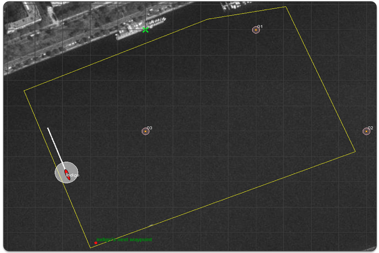
Figure 4.1: Simulated LBL Beacons: Three beacons are simulated, labelled 01, 02, and 03. The vehicle periodically issues a query to which the beacons immediately reply. The uFldBeaconRangeSensor application handles the queries and generates the range reports sent to each vehicle. The growing circles rendered around the vehicle and beacons represent the generation of the range query and range reports respectively.
The configuration for the uFldBeaconRangeSensor is shown in Listing 4.1 below. The three beacons are configured in lines 19-21. The configuration on line 7 indicates that a beacon query will be heard regardless of the range between the vehicle and the beacon. In the other direction, the range report from the beacon will only be heard if the vehicle is within 100 meters. Line 8 indicates that ping or range request will be honored by the simulator at most once every 30 seconds, and this clock is reset each time a range request is honored by the simulator with the configuration on line 9.
Listing 4.1 - Example configuration of the uFldBeaconRangeSensor application.
[[#brs_config]]
   1  ProcessConfig = uFldBeaconRangeSensor
   2  {
   3    AppTick   = 4   // Standard MOOSApp configurations
   4    CommsTick = 4
   5
   6    // Configuring aspects of the vehicles
   7    reach_distance = default = nolimit
   8    ping_wait      = 30
   9    ping_payments  = upon_accept
  10
  11    report_vars    = short
  12
  13    default_beacon_freq  = never       // Only on request (ping)
  14    default_beacon_shape = circle
  15    default_beacon_color = orange
  16    default_beacon_width = 5
  17    default_beacon_report_range = 100
  18
  19    beacon  = label=01, x=200, y=0
  20    beacon  = label=02, x=400, y=-200
  21    beacon  = label=03, x=0,   y=-200, color=red, shape=triangle, report_range=80
  22  }
The three beacons in this example are configured on lines 19-21 with unique labels and locations. Each beacon has additional properties, such as its shape, color and width when rendered. Default values for these properties are given in lines 14-16, but may be overridded for a particular beacon as on line 22.
The key configuration line in this example is on line 13 which indicates the beacons by default never generate an unsolicited range report. Reports are only generated upon request. In this example, the simulated vehicle would receive successive groups of BRS_RANGE_REPORT postings from all three simulated beacons, each time the vehicle posts a BRS_RANGE_REQUEST message to the MOOSDB. This example is runnable in the indigo example mission distributed with the MOOS-IvP source code and described a bit later in Section 7.
4.1 Configuring the Beacon Locations and Properties [top]
One or more beacons may be configured by the beacon configuration parameter provided in the uFldBeaconRangeSensor configuration block of the .moos file. Each beacon is configured with a line:
beacon = <configuration>
The <configuration> component is a comma-separated list of parameter=value pairs, with the following possible parameters: x, y, label, freq, shape, width, color, and query_range. The following are typical examples:
    beacon  = x=200, y=260, label=03, freq=10
    beacon  = x=-40, y=150, label=04, freq=5:15, color=red, shape=circle, width=4, report_range=200
The x and y parameters specify the beacon locations in local coordinates. Like several other MOOS applications, the uFldBeaconRangeSensor app looks for a global parameter in the .moos configuration file naming the position of the datum, or 0,0 position in latitude, longitude coordinates. The label parameter provides a unique identifier for the beacon. If a beacon entry is provided using a previously used label, the new beacon will overwrite the prior beacon in the simulator. If no label is provided, an automatic label will be generated equivalent to the index of the new beacon. The freq parameter specifies, in seconds, how often unsolicited range reports are generated for each beacon. A simple numerical value may be given, or a colon-separated pair of values as shown above may be used to specify a uniformly random interval of possible durations. The duration between posts will be reset after each post. The report_range parameter specifies the distance, in meters, that a vehicle must be to hear a range report generated by a beacon. The shape parameter indicates the shape used by applications like pMarineViewer when rendering the beacon. The uFldBeaconRangeSensor application generates a VIEW_MARKER post to the MOOSDB for each beacon, once upon startup of the simulator. The VIEW_MARKER structure and possible shapes are described in the pMarineViewer documentation. The color parameter specifies the color to be used when rendering the beacon. Legal color strings are described in the Color Appendix. The width parameter is used to indicate the width, in meters, when rendering the beacon.
For convenience, default values for several of the above properties may be provided with the following five supported configuration parameters:
   default_beacon_report_range = 100
   default_beacon_shape  = circle
   default_beacon_color  = orange
   default_beacon_width  = 4
   default_beacon_freq   = never
The above configuration values also represent all the default values. A beacon configuration that includes any of the above five parameters explicitly, will override any default values.
4.2 Unsolicited Beacon Range Reports [top]
The simulator may be configured to have all its beacons periodically generate a range report to all vehicles within range. The schedule of reporting may be uniform across all beacons, or individually set for each beacon. The interval of time between reports may also be set to vary according to a uniformly random time interval. By default, beacons are configured to never generate unsolicited range reports unless their frequency parameter is set to something else besides the default value of "never". The default value for all beacons may be configured with the following parameter in the uFldBeaconRangeSensor configuration block with the following:
default_beacon_freq = 120
The parameter value is given in seconds. To configure an interval to vary randomly on each post within a given range, e.g., somewhere between one and two minutes, the following may be used instead:
default_beacon_freq = 60:120
To configure the simulator to never generate an unsolicited range report, i.e., only solicited reports, use the following:
default_beacon_freq = never
Upon each range report post to the MOOSDB, the interval until the next post is recalculated. The beacon schedule may also be configured to be unique to a given beacon. The beacon configuration line accepts the freq parameter as described earlier in Section 4.1. The configuration provided for an individual beacon overrides the default frequency configuration.
Once a beacon has generated a report, it will not generate another unsolicited report until after the prevailing time interval has passed. However, if the simulator detects that the beacon has been solicited for a range report via an explicit range request from a nearby vehicle, a range report may be generated immediately. In this case the clock counting down to the beacon's next unsolicited report is reset.
4.3 Solicited Beacon Range Reports [top]
The uFldBeaconRangeSensor application accepts requests from vehicles, and may or may not generate one or more range reports for beacons within range of the vehicle making the request. In short, things operate like this: (a) a range request is received by uFldBeaconRangeSensor through its mailbox on the variable RANGE_REQUEST, (b) a determination is made as to whether the request is within range of the beacon and whether the request is allowed based on limits on the frequency of range requests, (c) a range report is generated and posted to the variable BRS_RANGE_REPORT. The following is an example of the range request format:
BRS_RANGE_REQUEST = "name=charlie"
Note that if a vehicle generates a range request triggering a range report from a beacon, the range report is sent to all vehicles within range of the beacon. Presumably the simulator has also received, at some point in the past, a node report, typically generated from the pNodeReporter application running on the vehicle. So the simulator not only knows which vehicle is making the range request, but also where that vehicle is located. It needs the vehicle location to determine the range between the vehicle and beacon, to generate the requested range report. The simulator also uses this range information to decide if it wants regard the beacon as being close enough to hear the request, and whether the vehicle is close enough to the beacon to hear the report.
4.4 Limiting the Frequency of Vehicle Range Requests [top]
From the perspective of operating a vehicle, one may ask: why not request a range report from all beacons as often as possible? There may be reasons why this is not feasible outside simulation. Limits may exist due to power budgets of the vehicle and/or beacons, and there may be prevailing communications protocols that make it at least impolite to be pushing range requests through a shared communications medium.
To reflect this limitation, the uFldBeaconRangeSensor application may be configured to limit the frequency in which a vehicle's range request (or ping) will be honored with a range report reply. By default this frequency is set to once every 30 seconds for all vehicles. The default for all vehicles may be changed with the following configuration in the .moos file:
ping_wait = default = 60
If the time interval as above is set to 60 seconds, what happens if a vehicle requests a range report 40 seconds after its previous request? Is it simply ignored, needing to wait another 20 seconds? Or is the clock reset to zero forcing the vehicle to wait 60 seconds before a ping is honored? By default, the former is the case, but the simulator may be configured to the more draconian option with:
ping_payments = upon_request
Suppose the minimum time interval has elapsed, but the querying/pinging vehicle is too far out of range from any beacon to hear even a single range report. Will the result be that the clock is reset to zero, forcing the vehicle to wait another 60 seconds before a query is honored? By default this is the case, but the simulator may be configured to not reset the clock unless the querying vehicle has received at least one range report for its query:
ping_payments = upon_response
In short, the simulator configuration parameter, ping_payments, may be configured with one of three options, "upon_request", "upon_response", or "upon_accept", with the default being the latter.
4.5 Producing Range Measurements with Noise [top]
In the default configuration of uFldBeaconRangeSensor, range reports are generated with the most precise range estimate as possible, with the only error being due to the latency of the communications generating the range request and range report. Additional noise/error may be added in the simulator for each range report with the following configuration parameter:
rn_algorithm = uniform,pct=0.12 // Values in the range [0,1]
Currently the only noise algorithm supported is the generation of uniformly random noise on the range measurement. The noise level, θ, set with the parameter rn_uniform_pct, will generate a noisy range from an otherwise exact range measurement r, by choosing a value in the range [{θ}{r}, r + {θ}{r} ]. The range without noise, i.e., the ground truth, may also be reported by the simulator if desired by setting the configuration parameter:
ground_truth = true
This will result in an additional MOOS variables posted, BRS_RANGE_REPORT_GT, with the same format as BRS_RANGE_REPORT, except the reported range will be given without noise.
5 Terminal and AppCast Output
The uFldBeaconRangeSensor application produces some useful information to the terminal and identical content through appcasting. An example is shown in Listing 5.1 below. On line 2, the name of the local community or vehicle name is listed on the left. On the right, "0/0(1478) indicates there are no configuration or run warnings, and the current iteration of uFldBeaconRangeSensor is 1478.
Lines 4-12: Beacon Configuration [top]
Lines 4-12 convey the prevailing beacon configuration settings. They may reflect the default values or values read from the configuration block like the one shown previously in Listing 2.2. Each beacon has an ID (first column), and the location in local coordinates in the next two columns. The fourth column indicates whether reports are generated in response to a poll, i.e., range request, or on a regular timed cycle as in beacon #03. If the latter type, the fifth column indicates the number of unsolicited pings generated. The Pings Recvd and Pings Gen'd columns show the number of range requests received and generated. Noise column indicates if there is any noise applied to the reports. The last two columns show the push and pull distances.
Listing 5.1 - Example uFldBeaconRangeSensor console or appcast output.
[[#lst_brs_appcast]]
   1  ===================================================================
   2  uFldBeaconRangeSensor hotel                               0/0(1478)
   3  ===================================================================
   4  Beacons(5):
   5                        Pings  Pings  Pings         Push  Pull
   6  ID     X     Y  Freq  Unsol  Recvd  Gen'd  Noise  Dist  Dist
   7  --  ----  ----  ----  -----  -----  -----  -----  ----  ----
   8  05   115  -150  poll  0      0      0      0      33    95
   9  04   -65  -345  poll  0      16     16     0      85    75
  10  03     0  -200  15.0  46     16     16     0      85    75
  11  02  -100  -100  poll  0      14     14     0      85    75
  12  01   200     0  poll  0      0      0      0      85    75
  13
  14  Vehicles(1):
  15         Push  Pull  Unsol  Pings  Pings  Too   Too
  16  VName  Dist  Dist  Rec'd  Gen'd  Rep'd  Freq  Far
  17  -----  ----  ----  -----  -----  -----  ----  ---
  18  hotel  100   100   22     24     46     0     74
  19
  20  ===================================================================
  21  Most Recent Events (8):
  22  ===================================================================
  23  [864.51]: Beacon[03]  ))-->  Range Broadcast to HOTEL
  24  [849.27]: Beacon[03]    -->  Range Reply to HOTEL
  25  [849.27]: Beacon[03]  <----  Ping from HOTEL
  26  [849.27]: Beacon[04]    -->  Range Reply to HOTEL
  27  [849.27]: Beacon[04]  <----  Ping from HOTEL
  28  [849.27]:   Range Request resets the clock for vehicle HOTEL
  29  [849.27]: Valid Range Request from HOTEL. Checking beacon ranges...
  30  [836.27]: Beacon[03]  ))-->  Range Broadcast to HOTEL
Unless the verbose setting is turned on, the output ending on line 37 above should be the last output written to the console for the duration of the simuator.
In the verbose mode, the simulator will produce event-based output as shown in the example above beginning on line 38. The asterisks in lines 39, 46, and 50 are not merely visual separators. An asterisk represents a single receipt of a NODE_REPORT message. Receiving node reports is essential for the operation of the simulator and this provides a bit of visual verification that this is occurring. Presumably node reports are being received much more often than range requests and range reports are handled, as is the case in the above example. The first time a node report is received for a particular vehicle, an announcement is made as shown on line 38.
In addition to handling incoming node reports, on any given iteration, the simulator may also handle an incoming range request, or may generate an unsolicited range report based on a beacon schedule. Console output for incoming range requests may look like that shown in lines 40-45 above. First the range request and the requesting vehicle is announced as online 40. The elapsed time since the vehicle last made a range request is shown as on line 41. If the request is honored by the simulator, this is indicated as shown on line 42. Otherwise a reason for denial may be shown. If the query is accepted, range reports may be generated for one or more vehicles. For each such vehicle, a line announcing the new report is generated, as in lines 43-45. On an iteration where unsolicited range reports are generated, output similar to that shown in lines 47-49 will generated. For each report, the beacon and receiving vehicle are named.
6 Interaction between uFldBeaconRangeSensor and pMarineViewer
The uFldBeaconRangeSensor application will post certain messages to the MOOSDB that may be subscribed for by GUI based applications like pMarineViewer for visualizing the posting of BRS_RANGE_REPORT and BRS_RANGE_REQUEST messages, as well as visualizing the beacon locations. A snapshot of the pMarineViewer window is shown below, with one vehicle and several beacons.
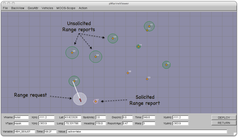
Figure 6.1: Beacons in the pMarineViewer: The VIEW_RANGE_PULSE message is passed to pMarineViewer to render unsolicited range reports (here in green), range requests from a vehicle (here in white), and solicited range reports in response to a range requeste (here in pink). The viewer alse renders the beacons and their labels upon receiving VIEW_MARKER messages posted by the uFldBeaconRangeSensor application. The pulses are only momemtarily visible until another VIEW_RANGE_PULSE message is received.
6.1 The VIEW_MARKER Data Structure [top]
The uFldBeaconRangeSensor application, upon startup, posts the beacon locations in the form of the VIEW_MARKER data structure. This MOOS variable is one of the default variables registered for by the pMarineViewer application. The types of supported markers are described in the pMarineViewer documentation. The marker type, size and color are configurable in the uFldBeaconRangeSensor configuration block. The user may use the variation in marker rendering to correspond to variation in beacon reporting or querying characteristics.
6.2 The VIEW_RANGE_PULSE Data Structure [top]
A range pulse message is used by the uFldBeaconRangeSensor application to convey visually the generation of a range report, or the receipt of a range request. The pulse is rendered as a ring with a growing radius having either the beacon or the vehicle at the center. A pulse eminating from a beacon indicates a range report, and a pulse eminating from a vehicle indicates a range request. By default different colors may be used for solicited and unsolicited range reports. In Figure 6.1 for example, the green rings represent unsolicited reports, the white ring represents a range request made by the vehicle, and the pink ring represents a response to the range request made by the one beacon within range to the vehicle.
The VIEW_RANGE_PULSE message is a data structure implemented in the XYRangePulse class, with the following format by example:
    VIEW_RANGE_PULSE = x=-40,y=-150,radius=40,duration=15,fill=0.25,fill_color=green,
                       label=04,edge_color=green,time=3892830128.5,edge_size=1
The x and y parameters convey the center of the pulse. The radius parameter indicates the radius of the circle at its maximum. The duration parameter is the number of seconds the pulse will be rendered. The pulse will grow its radius linearly from zero meters at zero seconds to radius meters at duration seconds. The fill parameter is in the range [0,1], where 0 is full transparency (clear) and 1 is fully opaque. The pulse transparency increases linearly as the range ring is rendered. The starting transparency at radius=0 is given by the fill parameter. The transparency at the maximum radius is zero. The fill_color parameter specifies the color rendered to the internal part of the range pulse. The choice of legal colors is described in the Colore Appendix. The label is a string that uniquely identifies the range instance to consumers like pMarineViewer. As with other objects in pMarineViewer, if it receives an object the same label and type as one previously received, it will replace the old object with the new one in its memory. The edge_color parameter describes the color of the ring rendered in the range pulse. The edge_size likewise describes the line width of the rendered ring. The time parameter indicates the UTC time at which the range pulse object was generated.
7 The Indigo Example Mission Using uFldBeaconRangeSensor
The indigo mission is distributed with the MOOS-IvP source code and contains a ready example of the uFldBeaconRangeSensor application, configured with three beacons acting as long baseline (LBL) beacons as described at the beginning of Section 4. Assuming the reader has downloaded the source code available at www.moos-ivp.org and built the code according to the documentation, the indigo mission may be launched by:
  $ cd moos-ivp/ivp/missions/s9_indigo/
  $ ./launch.sh 10
The argument, 10, in the line above will launch the simulation in 10x real time. Once this launches, the pMarineViewer GUI application should launch and the mission may be initiated by hitting the DEPLOY button. The vehicle will traverse a survey pattern over the rectangular operation region shown in Figure 4.1, periodically generating a range request to the three beacons. With each range request, a white range pulse should be visible around the vehicle. Almost immediately afterwards, a range report for each beacon is generated and a red range pulse around each beacon is rendered. The snapshot in Figure 4.1 depicts a moment in time where the range report visual pulses are beginning to grow around the beacons and the range request visual pulse is still visible around the one vehicle.
How does the simulated vehicle generate a range request? In practice a user may implement an intelligent module to reason about when to generate requests, but in this case the uTimerScript application is used by creating a script that repeats endlessly, generating a range request once every 25-35 seconds. The script is also conditioned on (NAV_SPEED > 0), so the pinging doesn't start until the vehicle is deployed. The configuration for the script can be seen in the uTimerScript configuration block in the indigo.moos file. More can be found in the uTimerScript documentation.
7.1 Examining the Log Data from the Indigo Mission [top]
After the launch script above has launched the simulation, the script should leave the console user with the option to "Exit and Kill Simulation" by hitting the '2' key. Once the vehicle has been deployed and traversed to one's satisfaction, exit the script. A log directory should have been created by the pLogger application in the directory where the simulation was launched. The directory name should be begin with MOOSLog_ with the remainder of the directory name composed from the timestamp of the launch.
Let's take a look at some of the data related to the simulation and uFldBeaconRangeSensor in particular. A dump of the entire file reveals a deluge of information. To look at the information relevant to the uFldBeaconRangeSensor application, the file is pruned with the aloggrep tool:
$ aloggrep MOOSLog_1_2_2011_____2_32_48.alog uFldBeaconRangeSensor uTimerScript
This produces a subset of the alog file similar to that shown in Listing 7.1, showing only log entries made by either the uFldBeaconRangeSensor application, or the uTimerScript application which generated all the range requests as described above. The first three posts made to the MOOSDB by uFldBeaconRangeSensor are the VIEW_MARKER posts representing a visual cue for the pMarineViewer application to render the three beacons.
Listing 7.1 - A subset of the data logged from the Indigo example mission's alog file.
[[#brs_indigo_alog]]
  %%%%%%%%%%%%%%%%%%%%%%%%%%%%%%%%%%%%%%%%%%%%%%%%%%%%%%%%%%%
  %% LOG FILE:       ./MOOSLog_22_2_2011_____17_27_06/MOOSLog_22_2_2011_____17_27_06.alog
  %% FILE OPENED ON  Tue Feb 22 17:27:06 2011
  %% LOGSTART               23371445284.8
  %%%%%%%%%%%%%%%%%%%%%%%%%%%%%%%%%%%%%%%%%%%%%%%%%%%%%%%%%%%
  55.697      VIEW_MARKER          uFldBeaconRangeSensor  x=0,y=-200,label=03,color=orange,type=circle,width=4
  55.698      VIEW_MARKER          uFldBeaconRangeSensor  x=400,y=-200,label=02,color=orange,type=circle,width=4
  55.698      VIEW_MARKER          uFldBeaconRangeSensor  x=200,y=0,label=01,color=orange,type=circle,width=4
  100.663     BRS_RANGE_REQUEST    uTimerScript           name=indigo
  100.846     VIEW_RANGE_PULSE     uFldBeaconRangeSensor  x=-97.65,y=-64.84,radius=50,duration=6,...
  100.846     BRS_RANGE_REPORT     uFldBeaconRangeSensor  vname=indigo,range=166.7446,id=03,time=23371445385.6
  100.846     VIEW_RANGE_PULSE     uFldBeaconRangeSensor  x=0,y=-200,radius=40,duration=15,...
  100.846     BRS_RANGE_REPORT     uFldBeaconRangeSensor  vname=indigo,range=515.6779,id=02,time=23371445385.6
  100.846     VIEW_RANGE_PULSE     uFldBeaconRangeSensor  x=400,y=-200,radius=40,duration=15,...
  100.847     BRS_RANGE_REPORT     uFldBeaconRangeSensor  vname=indigo,range=304.6305,id=01,time=23371445385.6
  100.847     VIEW_RANGE_PULSE     uFldBeaconRangeSensor  x=200,y=0,radius=40,duration=15,...
  160.419     BRS_RANGE_REQUEST    uTimerScript           name=indigo
  160.597     VIEW_RANGE_PULSE     uFldBeaconRangeSensor  x=-197.96,y=-129.16,radius=50,duration=6,...
  160.597     BRS_RANGE_REPORT     uFldBeaconRangeSensor  vname=indigo,range=210.2533,id=03,time=23371445445.3
  160.597     VIEW_RANGE_PULSE     uFldBeaconRangeSensor  x=0,y=-200,radius=40,duration=15,...
  160.597     BRS_RANGE_REPORT     uFldBeaconRangeSensor  vname=indigo,range=602.1416,id=02,time=23371445445.3
  160.597     VIEW_RANGE_PULSE     uFldBeaconRangeSensor  x=400,y=-200,radius=40,duration=15,...
  160.597     BRS_RANGE_REPORT     uFldBeaconRangeSensor  vname=indigo,range=418.3951,id=01,time=23371445445.3
  160.597     VIEW_RANGE_PULSE     uFldBeaconRangeSensor  x=200,y=0,radius=40,duration=15,...
The first range request is generated at time 100.663 by the uTimerScript. The uFldBeaconRangeSensor application receives this mail and posts a range pulse at time 100.846 conveying the range request from the vehicle, e.g., the white circle in Figure 4.1. The range request is met immediately and two posts are generated for each beacon. The VIEW_RANGE_PULSE message indicates the simulator has generated a range report for the beacon (the red circle in Figure 4.1. The BRS_RANGE_REPORT message is the actual range report to be used by the vehicle as it sees fit.
7.2 Generating Range Report Data for Matlab [top]
The log files generated as in Listing 7.1 above may processed to form a table of values suitable for Matlab processing. The alog2rng tool may be run on an alog file from the command line:
$ alog2rng MOOSLog_21_2_2011_____22_32_48.alog
This will generate a table of data like that below. The left column is the timestamp from the log file. The next N columns are the range measurements from each beacon. And the last three columns are the "ground truth" vehicle position and heading. The last three columns may be excluded with the --nav=false switch on the command line.
   Time       03          02          01          NAV_X      NAV_Y      NAV_HDG
   100.846    166.7446    515.6779    304.6305    -99.371    -65.917    238.000
   160.597    210.2533    602.1416    418.3951    -198.538   -130.397   197.456
   224.844    163.4205    558.5143    433.6937    -155.744   -248.991   159.000
The alog2rng tool is part of the Alog-Toolbox along with other tools for examining and modifying alog files generated by pLogger.
Document Maintained by: mikerb@mit.edu
Page built from LaTeX source using texwiki, developed at MIT. Errata to issues@moos-ivp.org. Get PDF