
- pMarineViewer
- uHelmScope
- Geometry Utilities
- uTimerScript
- pContactMgrV20
- uProcessWatch
- uLoadWatch
- pNodeReporter
- uXMS
- uSimMarineV22
- pMissionHash
- pMissionEval
- pHostInfo
- uPokeDB
- uQueryDB
- uMayFinish
- pEchoVar
- pDeadManPost
- pObstacleMgr
- iSay
- pRealm
- pSearchGrid
- pSpoofNode
- uTermCommand
- uSimCurrent
- uFldNodeBroker
- uFldShoreBroker
- uFldNodeComms
- uFldMessageHandler
- uFldBeaconRangeSensor
- uFldContactRangeSensor
- uFldCollisionDetect
- uFldCollObDetect
- uFldObstacleSim
- uFldScope
- uFldPathCheck
2.680 Competition Apps

Geometry Utilities
Maintained by: mikerb@mit.edu  Get PDF
1 Overview
2 General Geometric Object Properties
3 Points
3.1 String Representations for Points
4 Seglists
4.1 Standard String Representation for Seglists
4.2 The Lawnmower String Representation for Seglists
4.3 Seglists in the pMarineViewer Application
5 Polygons
5.1 Supported String Representation for Polygons
5.2 A Polygon String Representation using the Radial Format
5.3 A Polygon String Representation using the Ellipse Format
5.4 Optional Polygon Parameters
6 Seglrs
6.1 String Representations for Seglrs
6.2 Seglrs in the pMarineViewer Application
7 Vectors
7.1 String Representations for Vectors
7.2 Vectors in the pMarineViewer Application
1 Overview
This section discusses a few geometry data structures often used by the helm and the pMarineViewer application - convex polygons, lists of line segments, points, seglrs and vectors. These data structures are implemented by the classes XYPolygon, XYSegList, XYPoint, XYSeglr and XYVector respectively in the lib_geometry module distributed with the MOOS-IvP software bundle. The implementation of these class definitions is somewhat shielded from the helm user's perspective, but they are often involved in parameter settings of for behaviors. So the issue of how to specify a given geometric structure with a formatted string is discussed here.
Furthermore, the pMarineViewer application accepts these data structures for rendering by subscribing to three MOOS variables VIEW_POLYGON, VIEW_SEGLIST, mVIEW_POINT, anv VIEW_VECTOR. These variables contain a string format representation of the structure, often with further visual hints on the color or size of the edges and vertices for rendering. These variables may originate from any MOOS application, but are also often posted by helm behaviors to provide visual clues about what is going on in the vehicle. In the Alpha mission, for example, the waypoint behavior posted a seglist representing the set of waypoints for which it was configured, as well as posting a point indicating the next point on the behavior's list to traverse.
2 General Geometric Object Properties
Each of the four geometric objects, XYPolygon, XYSegList, XYPoint, and XYVector, are a subclass of the general XYObject class, and share certain properties discussed here.
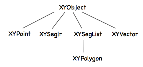
Figure 2.1: Class hierarchy: All geometric objects are subclasses of the XYObject class.
Common Properties [top]
The following properties are defined at the XYObject level. All properties may be optionally left undefined by the user.
- label: A string that is often rendered in a GUI alongside the object rendering. In the pMarineViewer application, the label is also used as a unique identifier and successive receipt of geometric objects with the same label will result in the new one replacing" the older one. Thus the visual effect of "moving" objects is rendered in this way.
- msg: A string typically regarded as an alternative to the label string when rendering an object. In the pMarineViewer application, if an object has a non-null msg field, this will be used for rendering the label instead of the label field.
- type: A string conveying some information on the type of the object from the source application. For example a point may be of type "waypoint" or "rendez-vous", and so on.
- time: The time field is a double that may optionally be set to indicate when the point was generated, or how long it should exist before “expiring”, or however an application may wish to interpret it.
- source: A string representing the source that generated the object. This may distinguish MOOS applications or helm behaviors for example.
Rendering Hint Properties [top]
The following optional properties are defined at the XYObject level for providing hints to applications that may be using them for rendering.
- active: This is a Boolean that is regarded as true if left unspecified, and is used to indicate whether or not the object should be rendered. By setting this value to false for a given object, it would effectively be erased in the pMarineViewer application for example.
- vertex_size: This non-negative floating point value is a hint for how large to draw a vertex point for the given object. If left unspecified in the pMarineViewer application for example, the size of the vertex would be determined by the global setting for vertices set in the GUI.
- edge_size: This non-negative floating point value is a hint for how wide to draw an edge for the given object (if it has edges). If left unspecified in the pMarineViewer application for example, the width of the edge would be determined by the global setting for edges set in the GUI.
- vertex_color: This parameter specifies a hint or request to draw the vertices in this object in the given color specification. Colors may be specified by any defined color string or RGB string value as described in the Colors Appendix. In the pMarineViewer application, if this hint is not provided for received objects, the vertex color would be determined by the global setting for vertices set in the GUI. If the color is set to "invisible", this is effectively a request that the vertex not be rendered.
- edge_color: This parameter specifies a hint or request to draw the edgees in this object in the given color specification. Colors may be specified by any defined color string or RGB string value as described in the Colors Appendix. In the pMarineViewer application, if this hint is not provided for received objects, the edge color would be determined by the global setting for edges set in the GUI. If the color is set to "invisible", this is effectively a request that the edge not be rendered.
- label_color: This parameter specifies a hint or request to draw the label for this object in the given color specification. Colors may be specified by any defined color string or RGB string value as described in the Colors Appendix. In the pMarineViewer application, if this hint is not provided for received objects, the label color would be determined by the global setting for labels set in the GUI. If the color is set to "invisible", this is effectively a request that label not be rendered.
3 Points
Points are implemented in the XYPoint class, and minimally represent a point in the x-y plane. These objects are used internally for applications and behaviors, and may also be involved in rendering in a GUI and therefore may have additional fields to support this as described in Section 2.
3.1 String Representations for Points [top]
The only required information for a point specification is its position in the x-y plane. A third value may optionally be specified in the z-plane. If z is left unspecified, it will be set to zero. The standard string representation is a comma-separated list of param=value pairs like the following examples:
  point   = x=60, y=-40
  point   = x=60, y=-40, z=12
  point   = z=19, y=5, x=23
Partly for backward compatibility, a very simplified string representation of a point is also supported:
  point   = 60,-40
  point   = 60, -40, 0
An example of string representation of point with all the optional parameters described in Section 2 might look something like:
  point   = x=60, y=-40, label=home, label_color=red, source=henry, type=waypoint,
            time=30, active=false, vertex_color=white, vertex_size=5, msg=bingo
Note that although a few different string formats are supported for specifying a point, only a single format is used when a XYPoint object is serialized into a string representation.
4 Seglists
Seglists are implemented in the XYSegList class and are comprised of an ordered set of vertices, implying line segments between each vertex. Seglist instances may be used for many things, but perhaps most often used to represent a set of vehicle waypoints. The geometry library has a number of basic operations defined for this class such as intersection testing with other objects, rotation, proximity testing and so on.
4.1 Standard String Representation for Seglists [top]
The only requirement for a seglist specification is one or more vertex locations in the x,y plane. Values may optionally be specified in the z plane. If z is left unspecified it will default to zero. The standard string representation is a comma-separated list of param=value pairs like the following examples:
points = pts={60,-40:60,-160:150,-160:180,-100:150,-40},label=foxtrot,type=top
By "standard" format we mean it is not only accepted as initialization input, but is also the format produced when an existing instance is serialized using the object's string XYSeglist::get_spec() function. If z values are used, an example may look like the following which is the same as the above but associates z=2 with each point:
points = pts={60,-40,2:60,-160,2:150,-160,2:180,-100,2:150,-40,2},label=foxtrot
An example of a string representation with all the optional parameters described in Section 2 might look something like:
  points = {pts=60,-40,2:60,-160,2:150,-160,2:180,-100,2:150,-40,2},label=foxtrot
           label_color=green, source=henry, type=return_path, time=30, active=false,
           vertex_color=white, vertex_size=5, edge_size=2, edge_color=red, msg=bingo
4.2 The Lawnmower String Representation for Seglists [top]
Seglists may also be built using the lawnmower format. The following is an example:
  points = format=lawnmower, label=foxtrot, x=0, y=40, height=60, width=180,
           lane_width=15, rows=north-south, startx=20, starty=-300, degs=45
The rotation of the pattern can optionally be specified in radians. For example, degs=45 is equivalent to rads=0.785398. If, for some reason, both are specified, the seglist will be built using the rads parameter.
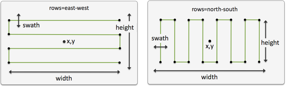
Figure 4.1: Seglists built with the lawnmower format: The pattern is specified by (a) the location of the center of the pattern, (b) the height and width of the pattern, (c) the lane width which determines the number of rows, (d) whether the pattern rows proceed north-south or east-west, and (e) an optional rotation of the pattern.
The startx and starty parameters name a point in the xy-plane to influence the starting position of the pattern. The seglist has four possible starting positions, and chosen starting position will be the position closest to the (startx, starty) position. The startx and starty parameters are optional and default to zero. Users sometimes may which to use a vehicle's present x-y position for these parameters.
4.3 Seglists in the pMarineViewer Application [top]
The pMarineViewer application registers for the MOOS variable VIEW_SEGLIST. The viewer maintains a list of seglists keyed on the label field of each incoming seglist. A seglist received with a thus far unique label will be added to the list of seglists rendered in the viewer. A seglist received with a non-unique label will replace the seglist with the same label in the memory of the viewer. This has the effect of erasing the old seglist since each iteration of the viewer redraws everything, the background and all objects, from scratch several times per second.
The label is the only text rendered with the seglist in pMarineViewer. Since the label is also used as the key, if the user trys to "update" the label, or use the label to convey changing information, this may inadvertently result in accumulating multiple seglists in the viewer, each drawn over one another. Instead, the VIEW_SEGLIST may be posted with the message to be posted in the msg=value component. When this component is non-null, pMarineViewer renders it instead of the contents in the label component.
5 Polygons
Polygons are implemented in the XYPolygon class. This implementation accepts as a valid construction only specifications that build a convex polygon. Common operations used internally by behaviors and other applications, such as intersection tests, distance calculations etc, are greatly simplified and more efficient when dealing with convex polygons.
5.1 Supported String Representation for Polygons [top]
The only requirement for a polygon specification is three or more vertex locations in the x,y plane constituting a convex polygon. Values may optionally be specified in the z plane. If z is left unspecified it will default to zero. The standard string representation is a comma-separated list of param=value pairs like the following examples:
points = pts={60,-40:60,-160:150,-160:150,-40},label=foxtrot,type=one
By "standard" format we mean it is not only accepted as initialization input, but is also the format produced when an existing instance is serialized using the object's string XYPolygon::get_spec() function. If z values are used, an example may look like the following which is the same as the above but associates z=4 with each point:
points = pts={60,-40,4:60,-160,4:150,-160,4:150,-40,4},label=foxtrot,type=one
Polygons are defined by a set of vertices and the simplest way to specify the points is with a line comprised of a sequence of colon-separated pairs of comma-separated x-y points in local coordinates such as:
polygon = 60,-40:60,-160:150,-160:180,-100:150,-40:label,foxtrot
If one of the pairs, such as the last one above, contains the keyword label on the left, then the value on the right, e.g., foxtrot as above, is the label associated with the polygon. An alternative notation for the same polygon is given by the following:
polygon = label=foxtrot, pts={60,-40:60,-160:150,-160:180,-100:150,-40}
This is an comma-separated list of equals-separated pairs. The ordering of the comma-separated components is insignificant. The points describing the polygon are provided in braces to signify to the parser that everything in quotes is the right-hand side of the pts= component. Both formats are acceptable specifications of a polygon in a behavior for which there is a polygon parameter.
5.2 A Polygon String Representation using the Radial Format [top]
Polygons may also be specified by their shape and the shape parameters. For example, a commonly used polygon is formed by points of an equal radial distance around a center point. The following is an example:
polygon = format=radial, label=foxtrot, x=0, y=40, radius=60, pts=6, snap=1
The snap component in the above example signifies that the vertices should be rounded to the nearest 1-meter value. The x, y parameters specify the middle of the polygon, and radius parameters specify the distance from the center for each vertex. The pts parameters specifies the number of vertices used, as shown in Figure 5.1.
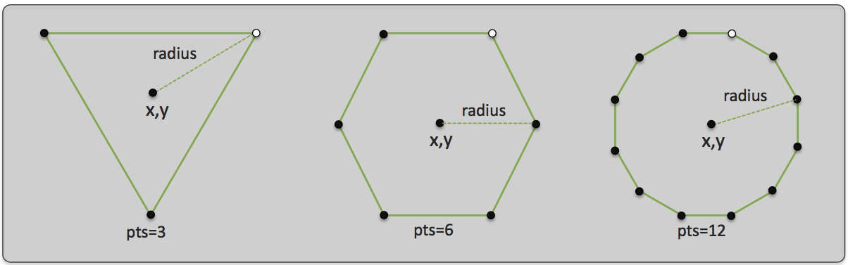
Figure 5.1: Polygons built with the radial format: Radial polygons are specified by (a) the location of their center, (b) the number of vertices, and (c) the radial distance from the center to each vertex. The lighter vertex in each polygon indicates the first vertex if traversing in sequence, proceeding clockwise.
5.3 A Polygon String Representation using the Ellipse Format [top]
Polygons may also be built using the ellipse format. The following is an example:
  polygon   = label=golf, format=ellipse, x=0, y=40, degs=45, pts=14, snap=1,
              major=100, minor=70
The x, y parameters specify the middle of the polygon, the major and minor parameters specify the radial distance of the major and minor axes. The pts parameters specifies the number of vertices used, as shown in Figure 5.2.
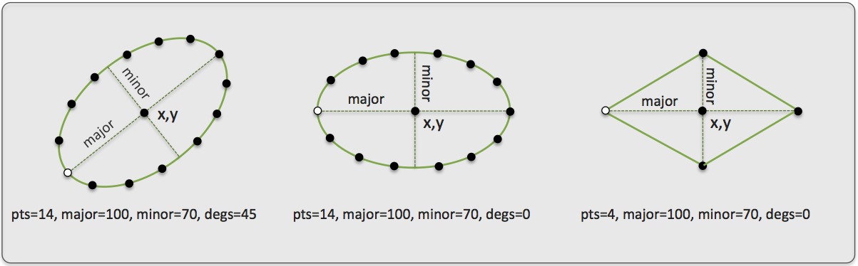
Figure 5.2: Polygons built with the ellipse format: Ellipse polygons are specified by (a) the location of their center, (b) the number of vertices, (c) the length of their major axis, (d) the length of their minor axis, and (e) the rotation of the ellipse.The lighter vertex in each polygon indicates the first vertex if traversing in sequence, proceeding clockwise.
The rotation of the ellipse can optionally be specified in radians. For example, degs=45 is equivalent to rads=0.785398. If, for some reason, both are specified, the polygon will be built using the rads parameter. When using the ellipse format, a minimum pts=4 must be specified.
5.4 Optional Polygon Parameters [top]
Polygons also may have several optional fields associated with them. The label field is string that is often rendered with a polygon in MOOS GUI applications such as the pMarineViewer. The label_color field represents a color preference for the label rendering. The type and source fields are additional string fields for further distinguishing a polygon in applications that handle them. The active field is a Boolean that is used in the pMarineViewer application to indicate whether the the polygon should be rendered. The time field is a double that may optionally be set to indicate when the polygon was generated, or how long it should exist before "expiring", or however an application may wish to interpret it. The vertex_color, edge_color, and vertex_size fields represent further rendering preferences. The following are two equivalent further string representations:
       polygon = format=radial, x=60, y=-40, radius=60, pts=8, snap=1, label=home,
                 label_color=red, source=henry, type=survey, time=30, active=true,
                 vertex_color=white, vertex_size=5, edge_size=2
       polygon = format,radial:60,-40:radius,60:pts,8:snap,1:label,home:
                 label_color,red:source,henry:type,survey:time,30:active,true:
                 vertex_color,white:vertex_size,5:edge_size,2
The former is a more user-friendly format for specifying a polygon, perhaps found in a configuration file for example. The latter is the string representation passed around internally when XYPolygon objects are automatically converted to strings and back again in the code. This format is more likely to be found in log files or seen when scoping on variables with one of the MOOS scoping tools.
6 Seglrs
Seglrs are implemented in the XYSeglr class and are essentially comprised of list of line segments followed by a ray. They may be used in certain applications to indicate a ship maneuver. Minimally each seglr consists of at least one vertext in the x,y plane (but typically more, indicating a series of line segments), and the direction of the ray. They may also be configured with all relevant drawing hints discussed in Section 2.
6.1 String Representations for Seglrs [top]
Seglr objects may be initialized from a string representation, and converted to a string representation from an existing object. The following is an example:
seglr = pts={5,5:30,10:90,-20},ray=45
The following is a string example using many of the general object fields and drawing hints available:
    seglr = pts={5,5:30,10:90,-20},ray=45,            <-- defines the seglr
            ray_len=10,head_size=3,                   <-- seglr drawing hints
            label=alpha,edge_color=red,edge_size=2,   <-- general object
            vertex_size=3,vertex_color=green          <--   drawing hints
The parameters, ray_len=10 and "head_size=3", are drawing hints unique to the seglr object and refers to how big the arrow head should be rendered and how long the ray should be rendered. They are given in meters, and the default is ray_len=10 and head_size=3.
6.2 Seglrs in the pMarineViewer Application [top]
The pMarineViewer application registers for the MOOS variable VIEW_SEGLR. The viewer maintains a list of seglrs keyed on the label field of each incoming seglr. A seglr received with a thus far unique label will be added to the list of seglrs rendered in the viewer. A seglr received with a non-unique label will replace the seglr with the same label in the memory of the viewer. This has the effect of erasing the old seglr since each iteration of the viewer redraws everything, the background and all objects, from scratch several times per second.
The VIEW_VECTOR may be posted with the message label, to be posted just beyond the arrow head. This is done with the msg component of the posting. For example:
   VIEW_SEGLR = pts={5,5:30,10:90,-20},ray=45,ray_len=10,head_size=3,  [=\=]
                label=alpha,edge_color=red,edge_size=2,msg=alpha
7 Vectors
Vectors are implemented in the XYVector class and are essentially comprised of a location, direction and magnitude. They may be used in certain applications dealing with simulated or sensed forces, or simply used in a GUI application to render current fields or an instantaneous vehicle pose and trajectory. Minimally each vector consists of a location in the x,y plane and a direction and magnitude. They may also be configured with all relevant drawing hints discussed in Section 2.
7.1 String Representations for Vectors [top]
Vector objects may be initialized from a string representation, and converted to a string representation from an existing object. The following is an example:
vector = x=5,y=10,ang=45,mag=20
Alternatively, instead of expressing the vector in terms of its direction and magnitude, it may also be given in terms of its magnitude in both the x and y direction. The following vector is nearly identical, modulo rounding errors, to the above configured vector:
vector = x=5,y=10,xdot=12.142,ydot=12.142
When a vector object is serialized to a string by invoking the object's native serialization function, the first of the two above formats will be used. The following is a string example using many of the general object fields and drawing hints available:
       vector = x=5,y=10,ang=45,mag=20,label=pingu,source=simulator,type=wind,
                vertex_size=2,vertex_color=red,edge_color=red,edge_size=2,head_size=12
The last parameter, "head_size=12", is a drawing hint unique to the vector object and refers to how big the arrow head should be rendered. If left unspecified, it may simply be rendered at whatever size the GUI application uses by default.
7.2 Vectors in the pMarineViewer Application [top]
The pMarineViewer application registers for the MOOS variable VIEW_VECTOR. The viewer maintains a list of vectors keyed on the label field of each incoming vector. A vector received with a thus far unique label will be added to the list of vectors rendered in the viewer. A vector received with a non-unique label will replace the vector with the same label in the memory of the viewer. This has the effect of erasing the old vector since each iteration of the viewer redraws everything, the background and all objects, from scratch several times per second.
The label is the only text rendered with the vector in pMarineViewer. Since the label is also used as the key, if the user trys to "update" the label, or use the label to convey changing information, this may inadvertently result in accumulating multiple vectors in the viewer, each drawn over one another. Instead, the VIEW_VECTOR may be posted with the message to be posted in the msg=value component. When this component is non-null, pMarineViewer renders it instead of the contents in the label component.
Document Maintained by: mikerb@mit.edu
Page built from LaTeX source using texwiki, developed at MIT. Errata to issues@moos-ivp.org. Get PDF