IvP Helm | Utils | Labs | Help


pShare
pLogger
pAntler
iRemote
pMarineViewer
uHelmScope
Geometry Utilities
uTimerScript
pBasicContactMgr
pContactMgrV20
uProcessWatch
uLoadWatch
pNodeReporter
uXMS
uSimMarineV22
uSimMarine
pHostInfo
uPokeDB
uQueryDB
pEchoVar
pObstacleMgr
pDeadManPost
iSay
pRealm
pSearchGrid
uTermCommand
uSimCurrent
The alogview Utility
Alog Command Line Utils
uMAC Utilities
Enabling Appcasting
On Demand Appcasting
uFldNodeBroker
uFldShoreBroker
uFldNodeComms
uFldMessageHandler
uFldHazardSensor
uFldHazardMgr
uFldHazardMetric
uFldBeaconRangeSensor
uFldContactRangeSensor
uFldCollisionDetect
uFldCollObDetect
uFldObstacleSim
uFldScope
uFldPathCheck
Appendix Colors
Appendix Logic
49 pMarineViewer: A GUI for Mission Monitoring and Control
49.1 Overview
49.1.1 The Shoreside-Vehicle Topology
49.1.2 Description of the pMarineViewer GUI Interface
49.1.3 The AppCasting, FullScreen and Traditional Display Modes
49.1.4 Run-Time and Mission Configuration
49.2 Command-and-Control
49.2.1 Configurable Pull-Down Menu Actions
49.2.2 Contextual Mouse Poking with Embedded OpArea Information
49.2.3 Action Button Configuration
49.2.4 Commander Pop-Up Window
49.3 The BackView Pull-Down Menu
49.3.1 Panning and Zooming
49.3.2 Background Images
49.3.3 Local Grid Hash Marks
49.3.4 Full-Screen Mode
49.4 The GeoAttributes Pull-Down Menu
49.4.1 Polygons, SegLists, Points, Circles and Vectors
49.4.2 Markers
49.4.3 Comms Pulses
49.4.4 Range Pulses
49.4.5 Drop Points
49.5 The Vehicles Pull-Down Menu
49.5.1 The Vehicle Name Mode
49.5.2 Dealing with Stale Vehicles
49.5.3 Supported Vehicle Shapes
49.5.4 Vehicle Colors
49.5.5 Centering the Image According to Vehicle Positions
49.5.6 Vehicle Trails
49.6 The AppCast Pull-Down Menu
49.6.1 Turning On and Off AppCast Viewing
49.6.2 Adjusting the AppCast Viewing Panes Height and Width
49.6.3 Adjusting the AppCast Refresh Mode
49.6.4 Adjusting the AppCast Fonts
49.6.5 Adjusting the AppCast Color Scheme
49.7 The MOOS-Scope Pull-Down Menu
49.8 The Action Pull-Down Menu
49.9 The Mouse-Context Pull-Down Menu
49.9.1 Generic Poking of the MOOSDB with the Operation Area Position
49.9.2 Custom Poking of the MOOSDB with the Operation Area Position
49.10 Configuring and Using the Commander Pop-Up Window
49.10.1 Commander Pop-Up Window Actions and Content
49.10.2 Commander Pop-Up Configuration
49.10.3 Commander Pop-Up Example Configuration from m2_berta Mission
49.10.4 Commander Pop-Up Coordination with pShare and uFldShoreBroker
49.11 Configuration Parameters for pMarineViewer
49.11.1 Configuration Parameters for the BackView Menu
49.11.2 Configuration Parameters for the GeoAttributes Menu
49.11.3 Configuration Parameters for the Vehicles Menu
49.11.4 Configuration Parameters for the AppCast Menu
49.11.5 Configuration Parameters for the Scope, MouseContext and Action Menus
49.12 Publications and Subscriptions for pMarineViewer
49.12.1 Variables Published by pMarineViewer
49.12.2 Variables Subscribed for by pMarineViewer
49.1 Overview [top]
The pMarineViewer application is a MOOS application written with FLTK and OpenGL for rendering vehicles and associated information and history during operation or simulation. A screen shot of a simple one-vehicle mission is shown below in Figure 49.1 .
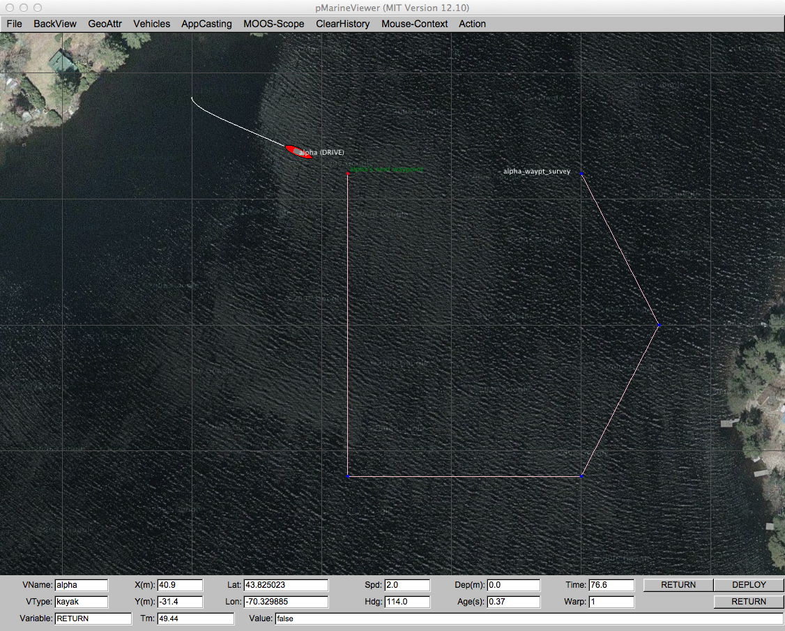
Figure 49.1: A pMarineViewer screen-shot executing a simple one-vehicle mission. The track of the vehicle is shown along with the set of waypoints it will traverse during this mission.
The user is able manipulate a geo display to see multiple vehicle tracks and monitor key information about individual vehicles. In the primary interface mode the user is a passive observer, only able to manipulate what it sees and not able to initiate communications to the vehicles. However there are hooks available and described later in this section to allow the interface to accept field control commands. With Release 12.11, appcasting viewing is supported to allow the pMarineViewer user to view appcasts across multiple fielded vehicles within a single optional window pane. This is described more fully in Section 49.6 .
49.1.1 The Shoreside-Vehicle Topology [top]
In some simple simulation single-vehicle arrangements pMarineViewer may co-exist in the same MOOS community as the helm and other components of a simulated vehicle. This is the case in the Alpha example mission. A more typical module topology, however, is that shown in Figure 49.2 , where pMarineViewer is running in its own dedicated local MOOS community while simulated vehicles, or real vehicles on the water, transmit information in the form of a stream of node reports to the local community.

Figure 49.2: A common usage of the pMarineViewer is to have it running in a local MOOSDB community while receiving node reports on vehicle poise from other MOOS communities running on either real or simulated vehicles. The vehicles can also send messages with certain geometric information such as polygons and points that the view will accept and render.
A key variable subscribed to by pMarineViewer is the variable NODE_REPORT, which has the following structure given by an example:
    NODE_REPORT = "NAME=henry,TYPE=uuv,TIME=1195844687.236,X=37.49,Y=-47.36,SPD=2.40,
                  HDG=11.17,LAT=43.82507169,LON=-70.33005531,TYPE=KAYAK,MODE=DRIVE,
                  ALLSTOP=clear,index=36,DEP=0,LENGTH=4"
Reports from different vehicles are sorted by their vehicle name and stored in histories locally in the pMarineViewer application. The NODE_REPORT is generated by the vehicles based on either sensor information, e.g., GPS or compass, or based on a local vehicle simulator.
In addition to node reports, pMarineViewer subscribes to several other types of information typically originating in the individual vehicle communities. This include several types of geometric shapes for which pMarineViewer has been written to handle. This includes points, polygons, lists of line segments, grids and so on. This is described further in Section 49.4 .
In addition to consuming the above information, pMarineViewer may also be configured to post certain information, usually for command and control purposes. Since this is mission-specific, this information is completely configured by the user to suit the mission. Posted information may also be tied to mouse clicks to allow, for example, a vehicle to be deployed to a point clicked by the users. This is described further in Section 49.2 .
49.1.2 Description of the pMarineViewer GUI Interface [top]
The viewable area of the GUI has three parts as shown in Figure 49.3 below. In the upper right, there is a geo display area where vehicles and perhaps other objects are rendered. The blue panes on the upper left displays appcast information. These panes hold appcast output from any appcast-enabled MOOS application running on any node, including the shoreside node. This is a new feature of Release 12.11 and may be toggled off and on with the 'a' key, and may be configured to be either open or closed by setting the appcast_viewable parameter inside the pMarineViewer MOOS configuration block.
In the lower pane, certain data fields associated with the active vehicle are updated. Multiple vehicles may be rendered simultaneously, but only one vehicle, the active will be reflected in the data fields in the lower pane. Changing the designation of which vehicle is active can be accomplished by repeatedly hitting the 'v' key. The active vehicle is always rendered as red, while the non-active vehicles have a default color of yellow. Individual vehicle colors can be given different default values (even red, which could be confusing) by the user.
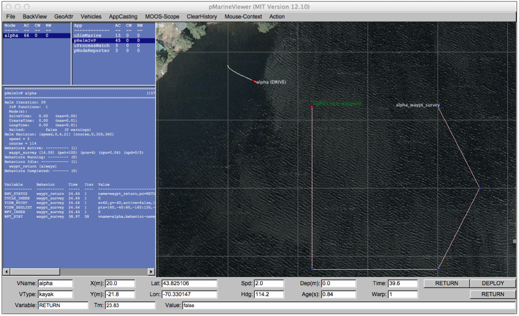
Figure 49.3: A screen shot of the pMarineViewer application running the alpha example mission. The position, heading, speed and other information related to the vehicle is reflected in the data fields at the bottom of the viewer.
Properties of the vehicle rendering such as the trail length, size, and color, and vehicle size and color, and pan and zoom can be adjusted dynamically in the GUI. They can also be set in the pMarineViewer MOOS configuration block. Both methods of tuning the rendering parameters are described later in this section. The individual fields of the data section are described below:
- VName: The name of the active vehicle associated with the data in the other GUI data fields. The active vehicle is typically indicated also by changing to the color red on the geo display.
- VType: The platform type, e.g., AUV, Glider, Kayak, Ship or Unknown.
- X(m): The x (horizontal) position of the active vehicle given in meters in the local coordinate system.
- Y(m): The y (vertical) position of the active vehicle given in meters in the local coordinate system.
- Lat: The latitude (vertical) position of the active vehicle given in decimal latitude coordinates.
- Lon: The longitude (horizontal) position of the active vehicle given in decimal longitude coordinates.
- Spd: The speed of the active vehicle given in meters per second.
- Hdg: The heading of the active vehicle given in degrees (0-359.99).
- Dep(m): The depth of the active vehicle given in meters.
- Age(s): The elapsed time in seconds since the last received node report for the active vehicle.
- Time: Time in seconds since pMarineViewer was launched.
- Warp: The MOOS Time-Warp value. Simulations may run faster than real-time by this warp factor. MOOSTimeWarp is set as a global configuration parameter in the .moos file.
The age of the node report is likely to remain zero in simulation as shown in the figure, but when operating on the water, monitoring the node report age field can be the first indicator when a vehicle has failed or lost communications. Or it can act as an indicator of communications link quality.
The lower three fields of the window are used for scoping on a single MOOS variable. See Section 49.7 for information on how to configure the pMarineViewer to scope on any number of MOOS variables and select a single variable via an optional pull-down menu. The scope fields are:
- Variable: The variable name of the MOOS variable currently being scoped, or "n/a" if no scope variables are configured.
- Time: The variable name of the MOOS variable currently being scoped, or "n/a" if no scope variables are configured.
- Value: The actual current value for the presently scoped variable.
49.1.3 The AppCasting, FullScreen and Traditional Display Modes [top]
As mentioned above, appcasting is new to release 12.11, pMarineViewer supports three display modes. The first mode is the normal mode familiar to pre-12.11 users of pMarineViewer as it was the only mode. A second mode, the appcasting mode, also shows the three appcasting panes shown above in Figure 49.3 . The third mode is the full-screen mode which shows only the geo-display part to maximize viewing of the operation area. The modes may be toggled by single hot-key actions as shown in the figure.
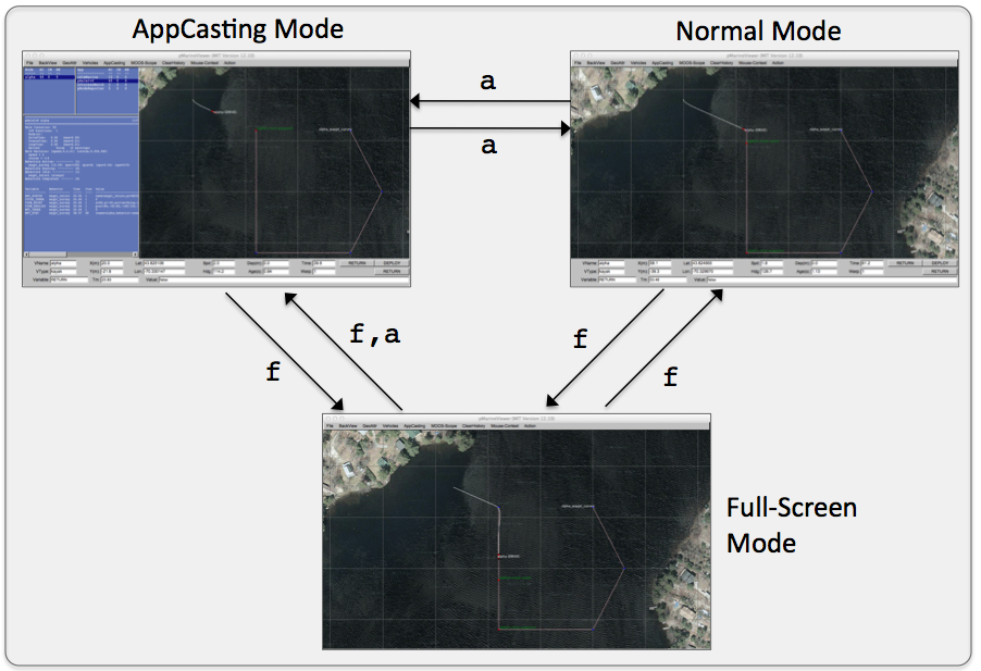
Figure 49.4: Three viewing modes are supported by pMarineViewer. The normal mode, the appcasting mode which renders appcast output from any connected vehicle, or the full-screen mode to maximize viewing of the operation area and vehicles. The modes may be toggled with the hot-keys shown. When typing 'f' in the full-screen mode, the viewer will return to the mode prior to entering the full-screen mode. The modes may also be changed via pull-down menu items, or set to personal preferences in the .moos configuration block.
To launch a mission in the appcasting mode, set appcast_viewable=true in the pMarineViewer configuration block. To launch in the full-screen mode, set full_screen=true in the configuration block instead.
49.1.4 Run-Time and Mission Configuration [top]
Nearly all pMarineViewer configuration parameters may be configured both at run-time, via pull-down menu selections, and prior to launch via configuration lines in the pMarineViewer configuration block of the .moos mission configuration file. To reduce the need to consult the documentation, the text of the pull-down menu selection is identical to the text of the parameter in the configuration file. Furthermore, most parameter selections are a choice from a fixed set of options. The present option for a parameter is typically indicated by a radio button in the pull-down menu.
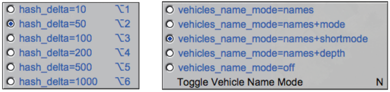
Figure 49.5: Most configuration parameters may be altered with pull-down menu selections. The radio-button shows the present parameter value and its neighbors show other legal settings. The text of the pull-down menu selection may be placed verbatim in the .moos configuration block to determine the setting upon the next mission launch. In general, menu items rendered in blue text are legally accepted parameters for placing in the .moos configuration block. Items in black are not.
Most parameter options have either a hot key associated with each option as shown in the left in Figure 49.5 , or a hot key for toggling between options as on the right in the figure.
49.2 Command-and-Control [top]
For the most part pMarineViewer is intended to be only a receiver of information from the vehicles and the environment. Adding command and control capability, e.g., widgets to re-deploy or manipulate vehicle missions, can be readily done, but make the tool more specialized, bloated and less relevant to a general set of users. However, pMarineViewer does have a few powerful extendible command and control capabilities under the hood. Each are simply ways to conveniently post to the MOOSDB, and come in three forms: (a) configurable pull-down menu actions, and (b) contextual mouse poking with embedded oparea information, (c) configurable action buttons, and in Release 17.7 and later, (d) a configure commander pop-up window.
49.2.1 Configurable Pull-Down Menu Actions [top]
The Action pull-down menu described in Section 49.8 provides a way to pre-define a set of MOOS postings, each selectable from the pull-down menu. For example, the alpha mission is configured with the below action:
action = RETURN = true
This post to the MOOSDB correlates to a behavior condition of the helm waypoint behavior with the return position. Actions may also be grouped into a single pull-down selection, discussed in Section 49.8 .
49.2.2 Contextual Mouse Poking with Embedded OpArea Information [top]
The mouse left and right buttons may be configured to make a post to the MOOSDB with value partly comprised of the point in the oparea under the mouse when clicked. For example, rather than commanding the vehicle to return to a pre-defined return position as the case above implies, the user may use this feature to command the vehicle to a point selected by the user at run time with a mouse click. The configuration might look like:
     left_context[return] = RETURN_POINT = points = $(XPOS),$(YPOS)
     left_context[return] = RETURN = true
This is discussed further in Section 49.9 .
49.2.3 Action Button Configuration [top]
Perhaps the most visible form of command and control is with the few action buttons configurable for on-screen use. For example, the DEPLOY and RETURN buttons in the lower right corner as in Figures 49.1 , and 49.3 . These buttons, for example, are configures as follows:
     button_one = DEPLOY # DEPLOY=true
     button_one = MOOS_MANUAL_OVERIDE=false # RETURN=false
     button_two = RETURN # RETURN=true
The general syntax is:
     button_one   = <label> # <MOOSVar>=<value> # <MOOSVar>=<value>  ...
     button_two   = <label> # <MOOSVar>=<value> # <MOOSVar>=<value>  ...
     button_three = <label> # <MOOSVar>=<value> # <MOOSVar>=<value>  ...
     button_four  = <label> # <MOOSVar>=<value> # <MOOSVar>=<value>  ...
The left-hand side contains one of the four button keywords, e.g., button_one. The right-hand side consists of a '#'-separated list. Each component in this list is either a '='-separated variable-value pair, or otherwise it is interpreted as the button's label. The ordering does not matter and the '#'-separated list can be continued over multiple lines as in the simple example above.
The variable-value pair being poked on a button call will determine the variable type by the following rule of thumb. If the value is non-numerical, e.g., true, one, it is poked as a string. If it is numerical it is poked as a double value. If one really wants to poke a string of a numerical nature, the addition of quotes around the value will suffice to ensure it will be poked as a string.
49.2.4 Commander Pop-Up Window [top]
In Releases 17.7 the commander pop-up feature was added to pMarineViewer. This can be thought of as the tool to use when your mission requires the more than the four buttons allowed on the lower right corner of the main screen (the Action Buttons described above in Section 49.2.3 . The commander pop-up window contains user-configured commands to either all vehicles, or particular vehicles, and commands to the shoreside if desired. If pMarineViewer is configured to use the commander pop-up, this window is toggled open/closed with the spacebar key. It also contains a log at the bottom of the window, showing exactly what pokes to the MOOSDB are made upon each button click.
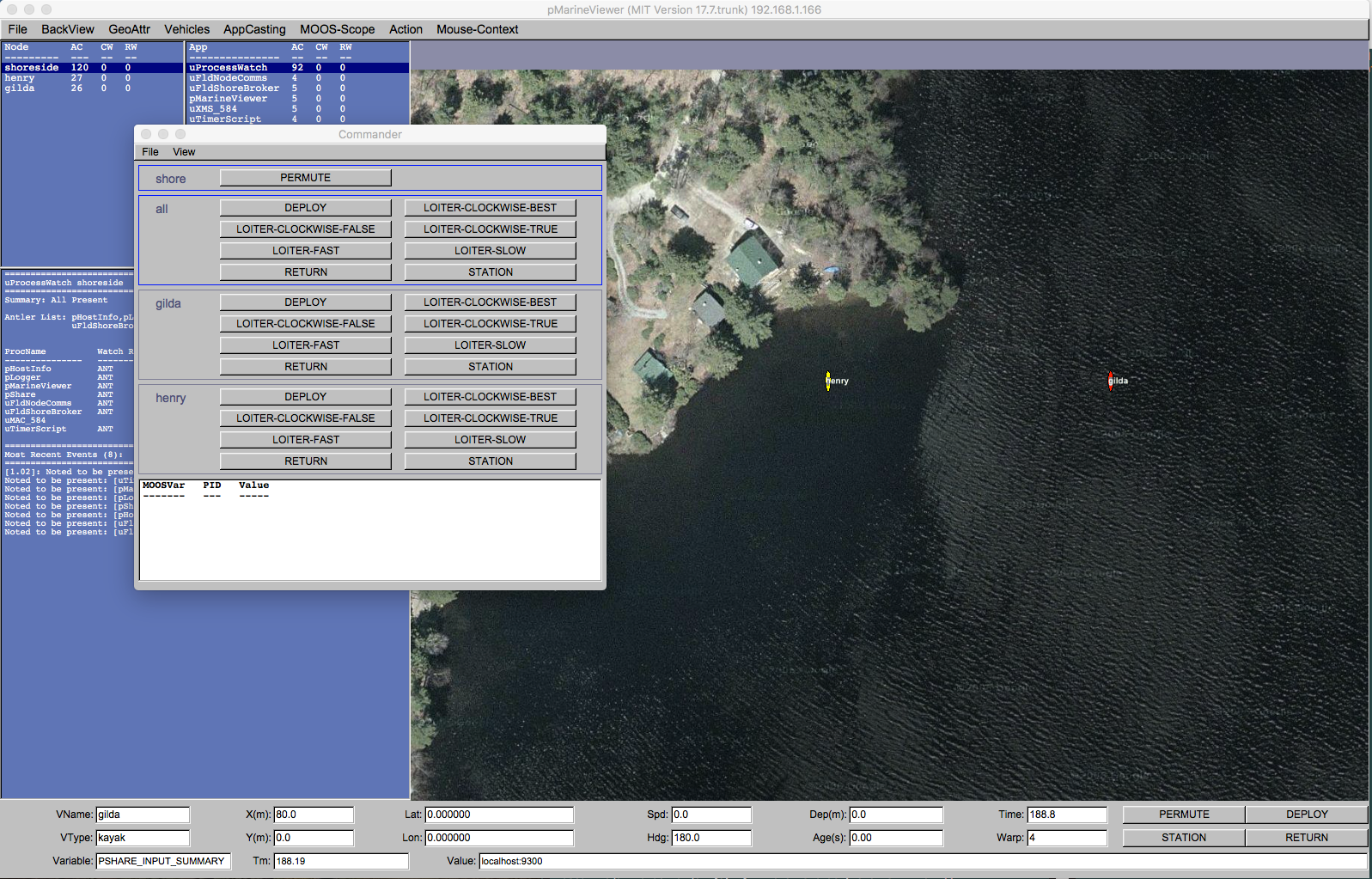
Figure 49.6: The commander pop-up window is toggled open/closed with the space-bar key and presents the user with a set of user-configured commands to either the all vehicles, individual vehicles, or the the pMarineViewer shoreside community itself.
The above figure was generated from the m2_berta mission, which may be used as a good starting example. This pop-up window is configured in the pMarineViewer configuration block as described further in Section 49.10 .
49.3 The BackView Pull-Down Menu [top]
The BackView pull-down menu deals mostly with panning, zooming and issues related to the rendering of the background on which vehicles and mission artifacts are rendered. The full menu is shown in Figure 49.7 .
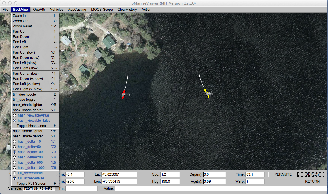
Figure 49.7: The BackView menu: This pull-down menu lists the options, with hot-keys, for affecting rendering aspects of the geo-display background.
Although panning and zooming is not something typically done via the pull-down menu, they are included in this menu primarily to remind the user of their hot-keys. The zooming commands affect the viewable area and apparent size of the objects. Zoom in with the 'i' or 'I' key, and zoom out with the 'o' or 'O' key. Return to the original zoom with ctrl+'z'.
49.3.1 Panning and Zooming [top]
Panning is done with the keyboard arrow keys. Three rates of panning are supported. To pan in 20 meter increments, just use the arrow keys. To pan "slowly" in one meter increments, use the Alt + arrow keys. And to pan "very slowly", in increments of a tenth of a meter, use the Ctrl + arrow keys. The viewer supports two types of "convenience" panning. It will pan to put the active vehicle in the center of the screen with the 'C' key, and will pan to put the average of all vehicle positions at the center of the screen with the 'c' key. These are part of the 'Vehicles' pull-down menu discussed in Section 49.5 .
49.3.2 Background Images [top]
The background can be in one of two modes; either displaying a gray-scale background, or displaying a geo image read in as a texture into OpenGL from an image file. The default is the geo display mode if provided on start up, or the grey-scale mode if no image is provided. The mode can be toggled by typing the 'b' or 'B' key. The geo-display mode can have two sub-modes if two image files are provided on start-up. This is useful if the user has access to a satellite image and a map image for the same operation area. The two can be toggled by hitting the back tick key. When in the grey-scale mode, the background can be made lighter by hitting the ctrl+'b' key, and darker by hitting the alt+'b' key.
To use an image in the geo display, the input to pMarineViewer comes in two files, an image file in TIFF format, and an information text file correlating the image to the local coordinate system. The file names should be identical except for the suffix. For example dabob_bay.tif and dabob_bay.info. Only the .tif file is specified in the pMarineViewer configuration block of the MOOS file, and the application then looks for the corresponding .info file. The info file correlates the image to the local coordinate system and specifies the location of the local (0,0) point. An example is given in Listing 49.1 .
Listing 49.1 - An example .info file associated with a background image.
  1  // Lines may be in any order, blank lines are ok
  2  // Comments begin with double slashes
  3
  4  datum_lat  = 47.731900
  5  datum_lon  = -122.85000
  6  lat_north  = 47.768868
  7  lat_south  = 47.709761
  8  lon_west   = -122.882080
  9  lon_east   = -122.794189
All four latitude/longitude parameters are mandatory. The two datum lines indicate where (0,0) in local coordinates is in earth coordinates. However, the datum used by pMarineViewer is determined by the LatOrigin and LongOrigin parameters set globally in the MOOS configuration file. The datum lines in the above information file are used by applications other than pMarineViewer that are not configured from a MOOS configuration file. The lat_north parameters correlate the upper edge of the image with its latitude position. Likewise for the other three parameters and boundaries. Two image files may be specified in the pMarineViewer configuration block. This allows a map-like image and a satellite-like image to be used interchangeably during use. An example of this is shown in Figure 49.8 with two images of Dabob Bay in Washington State. Both image files where created from resources at www.maps.google.com.
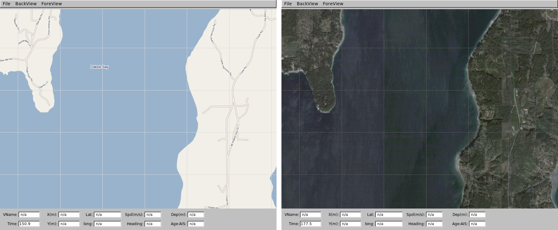
Figure 49.8: Dual background geo images: Two images loaded for use in the geo display mode of pMarineViewer. The user can toggle between both as desired during operation.
In the configuration block, the images can be specified by:
     tiff_file   = dabob_bay_map.tif
     tiff_file_b = dabob_bay_sat.tif
By default pMarineViewer will look for the files Default.tif and DefaultB.tif in the local directory unless alternatives are provided in the configuration block.
By default a copies of the background image and info files are not logged by pLogger. This may be changed by the setting the following parameter: log_the_image = true. This is only a request to pLogger in the form of the PLOGGER_CMD posting:
     PLOGGER_CMD = COPY_FILE_REQUEST = /home/jake/images/lake_george.tif
     PLOGGER_CMD = COPY_FILE_REQUEST = /home/jake/images/lake_george.info
The result should be that the files are included in the folder created by pLogger with the ._tif and ._info suffixes. These may then be used by post-mission analysis tools to re-convey the operation area.
49.3.3 Local Grid Hash Marks [top]
Hash marks can be overlaid onto the background. By default this mode is off, but can be toggled with the 'h' or 'H' key, or set in the configuration file with the hash_viewable parameter. The hash marks are drawn in a grey-scale which can be made lighter by typing the ctrl+'h' key, and darker by typing the alt+'h' key, or set in the configuration file with the hash_shade parameter. The hash mark spacing may only be set to one of the values shown in the menu. If set to different value, the closest legal value will be chosen.
49.3.4 Full-Screen Mode [top]
The viewer may be put into full-screen mode by toggling with the 'f' key. This will result in the data fields at the bottom of the viewer being replace with a bit more viewing area for the geo display. As with all other blue items in this pull-down menu, the full-screen mode may be set in the MOOS configuration block with full_screen=true. The default if false. Full-screen mode is useful when running simulations while connected to a low-resolution projector for example.
49.4 The GeoAttributes Pull-Down Menu [top]
The GeoAttributes pull-down menu allows the user to affect viewing properties of geometric objects capable of being rendered by the pMarineViewer. The viewer subscribes for and supports the following geometric objects, typically generated by the helm or other MOOS applications:
- Polygons
- SegLists
- Points
- Vectors
- Circles
- Markers
- RangePulses
- CommsPulses
The viewer will also render the following other geometric objects set either in the configuration file or interactively by the user:
- Datum
- OpArea
- DropPoints
The Datum is simply the point in local coordinates representing (0,0). The pull-down menu allows the user to toggle off or on this rendering of the datum point as well as adjust its size and color. The OpArea is used to render the boundaries, if they exist, of an area of operation. DropPoints (described further in Section 49.4.7 ) are labeled points the user may drop on the viewing area for reference or mission planning
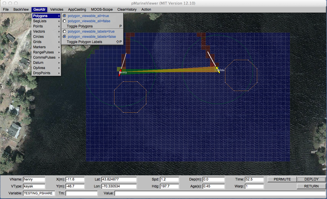
Figure 49.9: The "GeoAttr" menu: This pull-down menu lists the options and hot keys for affecting the rendering of geometric objects.
The possible parameters settings for rendering the geometric objects received by pMarineViewer via MOOS mail is provided in Section 49.11.2 .
49.4.1 Polygons, SegLists, Points, Circles and Vectors [top]
The five geometric objects, polygons, seglists, points, circles and vectors, provide a core rendering capability for applications (like the helm and its behaviors) to render visual artifacts related to the unfolding of a mission. For example, in Figure 49.1 , a seglist is used to render the vehicle waypoints, and a labeled point is used to render the vehicles current next waypoint.
Objects are passed to pMarineViewer as strings via normal MOOS mail. An example is given below for the seglist shown in Figure 49.1 . The string is a comma-separated list of variable=value pairs. Note the last pair is a label. Labels are used by all five object types to distinguish uniqueness.
VIEW_SEGLIST = pts={60,-40:60,-160:150,-160:180,-100:150,-40},label=waypt_survey
Uniqueness is used to either overwrite or erase previously rendered object instances. For example the above seglist could be "moved" five meters south by posting an identical message with the same label and adjusted coordinates. The source of the object is also tracked by pMarineViewer. This is given by the MOOS community from which the message originated, and typically represents the vehicle's name. Thus the above seglist could also be "moved" if the posting originated from a second vehicle community, in the type of arrangement shown in Figure 49.2 .
Parameters Common to Polygons, SegLists, Points, Circles and Vectors [top]
Other optional parameters may be associated with an object to specify rendering preferences. They include:
- active
- msg
- vertex_size:
- vertex_color
- edge_size
- edge_color
- fill_color
- fill_transparency
For example, the VIEW_SEGLIST specification above may be augmented with the below string to specify edge and vertex size and color preferences:
edge_color=pink,vertex_color=blue,vertex_size=4,edge_size=1
The active parameter may be set to false to indicate that an object, previously received with the same label, should not be drawn by pMarineViewer. The msg parameter may be used to override the string rendered as the object's label. Since labels are used to uniquely identify an object, the msg parameter may be used to, for example, draw five points all with same rendered text. The other six parameters are self-explanatory and not necessarily relevant to all objects. For example, pMarineViewer will ignore an edge_size specification when drawing a point, and a fill_color will only be relevant for a polygon and a circle.
Serializing Geometric Objects for pMarineViewer Consumption [top]
Geometric objects are only consumed by pMarineViewer, but it's worth discussing the issue of generating and serializing an object into a string. It is possible to simply post a string in the right format, as with:
   string str = "x=5,y=25,label=home,vertex_size=3";  // Not recommended
   m_Comms.Notify("VIEW_POINT", str);
It is highly recommended that this be left to the serialization function native to the C++ class.
   #include "XYPoint.h"

   XYPoint my_point(5, 25);                           // Recommended
   my_point.set_label("home");
   my_point.set_vertex_size(3);
   string str = my_point.get_spec();
   m_Comms.Notify("VIEW_POINT", str);
The latter code is less prone to user error, and is more likely to work in future code releases if the underlying formats need to be altered. (This is the idea behind Google Protocol Buffers, but here the geometric classes are implemented with various geometry function relations defined in addition to the serialization and de-serialization.) The full set of interface possibilities for creating and manipulating geometry objects is beyond the scope of the discussion here however.
49.4.2 Markers [top]
A set of marker object types are defined for rendering characteristics of an operation area such as buoys, fixed sensors, hazards, or other things meaningful to a user. The six types of markers are shown in Figure 49.10 . They are configured in the pMarineViewer configuration block of the MOOS file with the following format:
   marker  = type=efield,x=100,y=20,label=alpha,color=red,width=4.5
   marker  = type=square,lat=42.358,lon=-71.0874,color=blue,width=8
Each entry is a string of comma-separated pairs. The order is not significant. The only mandatory fields are for the marker type and position. The position can be given in local x-y coordinates or in earth coordinates. If both are given for some reason, the earth coordinates will take precedent. The width parameter is given in meters drawn to scale on the geo display. Shapes are roughly 10x10 meters by default. The GUI provides a hook to scale all markers globally with the ALT-m and CTRL-m hot keys and in the GeoAttributes pull-down menu.
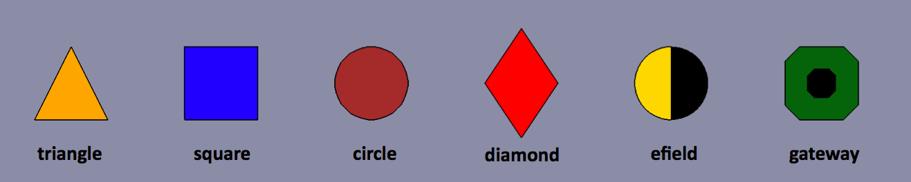
Figure 49.10: Markers: Types of markers known to the pMarineViewer.
The color parameter is optional and markers have the default colors shown in Figure 49.10 . Any of the colors described in the Colors Appendix are fair game. The black part of the Gateway and Efield markers is immutable. The label field is optional and is by default the empty string. Note that if two markers of the same type have the same non-empty label, only the first marker will be acknowledged and rendered. Two markers of different types can have the same label.
In addition to declaring markers in the configuration file, markers can be received dynamically by pMarineViewer through the VIEW_MARKER MOOS variable, and thus can originate from any other process connected to the MOOSDB. The syntax is exactly the same, thus the above two markers could be dynamically received as:
     VIEW_MARKER  = "type=efield,x=100,y=20,scale=4.3,label=alpha,color=red,width=4.5"
     VIEW_MARKER  = "type=square,lat=42.358,lon=-71.0874,scale=2,color=blue,width=8"
The effect of a "moving" marker, or a marker that changes color, can be achieved by repeatedly publishing to the VIEW_MARKER variable with only the position or color changing while leaving the label and type the same. To dynamically alter the text rendered with a marker, the msg=value field may be used instead. When the message is non-empty, it will be rendered instead of the label text.
49.4.3 Comms Pulses [top]
Comms pulse objects were designed to convey a passing of information from one node to another. At this writing, they are only used by the uFldNodeComms application, but from the perspective of pMarineViewer it does not matter the origin. The MOOS variable is VIEW_COMMS_PULSE. They look something like that shown in Figure 49.11 . There are two pulses shown in this figure. In this case they were posted by uFldNodeComms to indicate that the two vehicles are receiving each other's node reports.
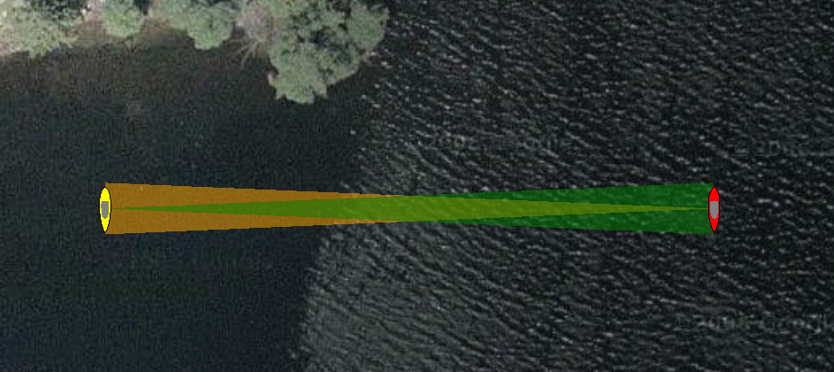
Figure 49.11: Comms Pulses: A comms pulse directionally renders communication between vehicles. Here each vehicle is communicating with the other, and two different colored pulses are rendered.
The term "pulse" is used because the object has a duration (by default three seconds), after which it will no longer be rendered by pMarineViewer. The pulse will fade (become more transparent) linearly with time as it approaches its expiration. If a subsequent comms pulse is received with an identical label before the first pulse times out, the second pulse will replace the first, in the style of other geometric objects discussed previously. Although serializing and de-serializing comms pulse messages is outside the scope of this discussion, it it worth examining an example comms pulse message:
   VIEW_COMMS_PULSE = sx=91,sy=29,tx=6.7,ty=1.4,beam_width=7,duration=10,fill=0.35,
                      label=GILDA2HENRY_MSG,fill_color=white,time=1350201497.27
As with the object types discussed previously, the construction of the above type messages should be handled by the XYCommsPulse class along the line of something like:
   #include "XYCommsPulse.h"

   XYCommsPulse my_pulse(91, 29, 6.7, 1.4);
   my_pulse.set_label("GILDA2HENRY_MSG");
   my_pulse.set_duration(10);
   my_pules.set_beam_width(7);
   my_pules.set_fill(0.35);
   my_pulse.set_color("fill", "white");
   string str = my_pulse.get_spec();
   m_Comms.Notify("VIEW_COMMS_PULSE", str);
The white comms pulse shown in Figure 49.12 indicates that a message has been sent from one vehicle to the other. The fat end of the pulse indicates the receiving vehicle. The color scheme is not a convention of pMarineViewer, but rather a convention of the uFldNodeComms application which generated the object in this case. A white pulse is typically rendered long enough to allow the user to visually register the information. It also typically does not move with the vehicle, to convey to the user the vehicle positions at the time of the communication.
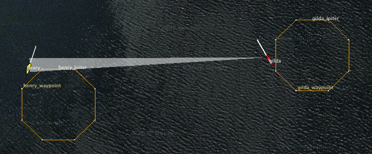
Figure 49.12: Comms Pulses for Messaging: In this figure the white comms pulse indicates that a message is being sent from one vehicle to another, via uFldNodeComms.
in pMarineViewer via a selection in the GeoAttr pull-down menu, or via the '@' hot key. It is not possible in pMarineViewer to show just the white comms pulses, and hide the colored node report comms pulses, or vice versa. It is possible however in the uFldNodeComms configuration to shut off the node report pulses with view_node_rpt_pulses=false.
49.4.4 Range Pulses [top]
Range pulse objects were designed to convey a passing of information or sensor energy from one node to any other node in the vicinity, up to a certain range. At this writing they are only used by the uFldContactRangeSensor and uFldBeaconRangeSensor applications, but from the perspective of pMarineViewer it does not matter the origin. The MOOS variable is VIEW_RANGE_PULSE. They look something like that shown in Figure 49.13 . Here the pulse is shown over three successive times.
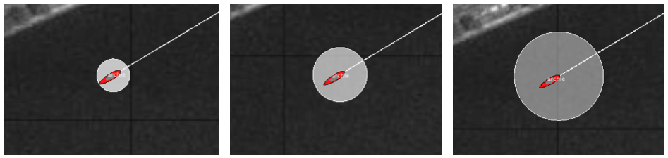
Figure 49.13: Comms Pulses: A comms pulse directionally renders communication between vehicles. Here each vehicle is communicating with the other, and two different colored pulses are rendered.
The term "pulse" is used because the object has a duration (by default 15 seconds), after which it will no longer be rendered by pMarineViewer. The pulse will grow in size and fade (become more transparent) linearly with time as it approaches its expiration. If a subsequent range pulse is received with an identical label before the first pulse times out, the second pulse will replace the first, in the style of other geometric objects discussed previously. Although serializing and de-serializing range pulse messages is outside the scope of this discussion, it it worth examining an example range pulse message:
   VIEW_RANGE_PULSE = x=99.2,y=68.9,radius=50,duration=6,fill=0.9,label=archie_ping,
                      edge_color=white,fill_color=white,time=2700438154.35,edge_size=1
As with the object types discussed previously, the construction of the above type messages should be handled by the XYRangePulse class along the line of something like:
   #include "XYRangePulse.h"

   XYRangePulse my_pulse(99.2, 68.9);
   my_pulse.set_label("archie_ping");
   my_pulse.set_duration(6);
   my_pules.set_edge_size(1);
   my_pules.set_radius(50);
   my_pules.set_fill(0.9);
   my_pulse.set_color("edge", "white");
   my_pulse.set_color("fill", "white");
   string str = my_pulse.get_spec();
   m_Comms.Notify("VIEW_RANGE_PULSE", str);
49.4.5 Drop Points [top]
A user may be interested in determining the coordinates of a point in the geo portion of the pMarineViewer window. The mouse may be moved over the window and when holding the SHIFT key, the point under the mouse will indicate the coordinates in the local grid. When holding the CTRL key, the point under the coordinates are shown in lat/lon coordinates. The coordinates are updated as the mouse moves and disappear thereafter or when the SHIFT or CTRL keys are release. Drop points may be left on the screen by hitting the left mouse button at any time. The point with coordinates will remain rendered until cleared or toggled off. Each click leaves a new point, as shown in Figure 49.14 .
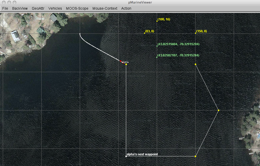
Figure 49.14: Drop points: A user may leave drop points with coordinates on the geo portion of the pMarineViewer window. The points may be rendered in local coordinates or in lat/lon coordinates. The points are added by clicking the left mouse button while holding the SHIFT key or CTRL key. The rendering of points may be toggled on/off, cleared in their entirety, or reduced by popping the last dropped point.
Parameters regarding drop points are accessible from the GeoAttr pull-down menu. The rendering of drop points may be toggled on/off by hitting the 'r' key. Drop points may also be shut off in the mission configuration file with drop_point_viewable_all=false. The set of drop points may be cleared in its entirety via the pull-down menu. Or the most recently dropped point may be removed by typing the CTRL-r key. The pull-down menu may also be used to change the rendering of coordinates from "as-dropped" where some points are in local coordinates and others in lat/lon coordinates, to "local-grid" where all coordinates are rendered in the local grid, or "lat-lon" where all coordinates are rendered in the lat/lon format. By default the mode is "as-dropped". The startup default mode may be changed with drop_point_coords=local-grid for example in the mission file.
49.5 The Vehicles Pull-Down Menu [top]
The Vehicles pull-down menu deals with rendering properties of vehicles, vehicle labels, and vehicle trails. The options are shown in Figure 49.15 . The very first option is to turn on or off the rendering of all vehicles. The can be done at run time via the menu selection, or toggled with the Ctrl-'a' hot key. Like all blue options in this menu, the text in the menu item may be placed verbatim in the mission configuration file to reflect the user's startup preferences.
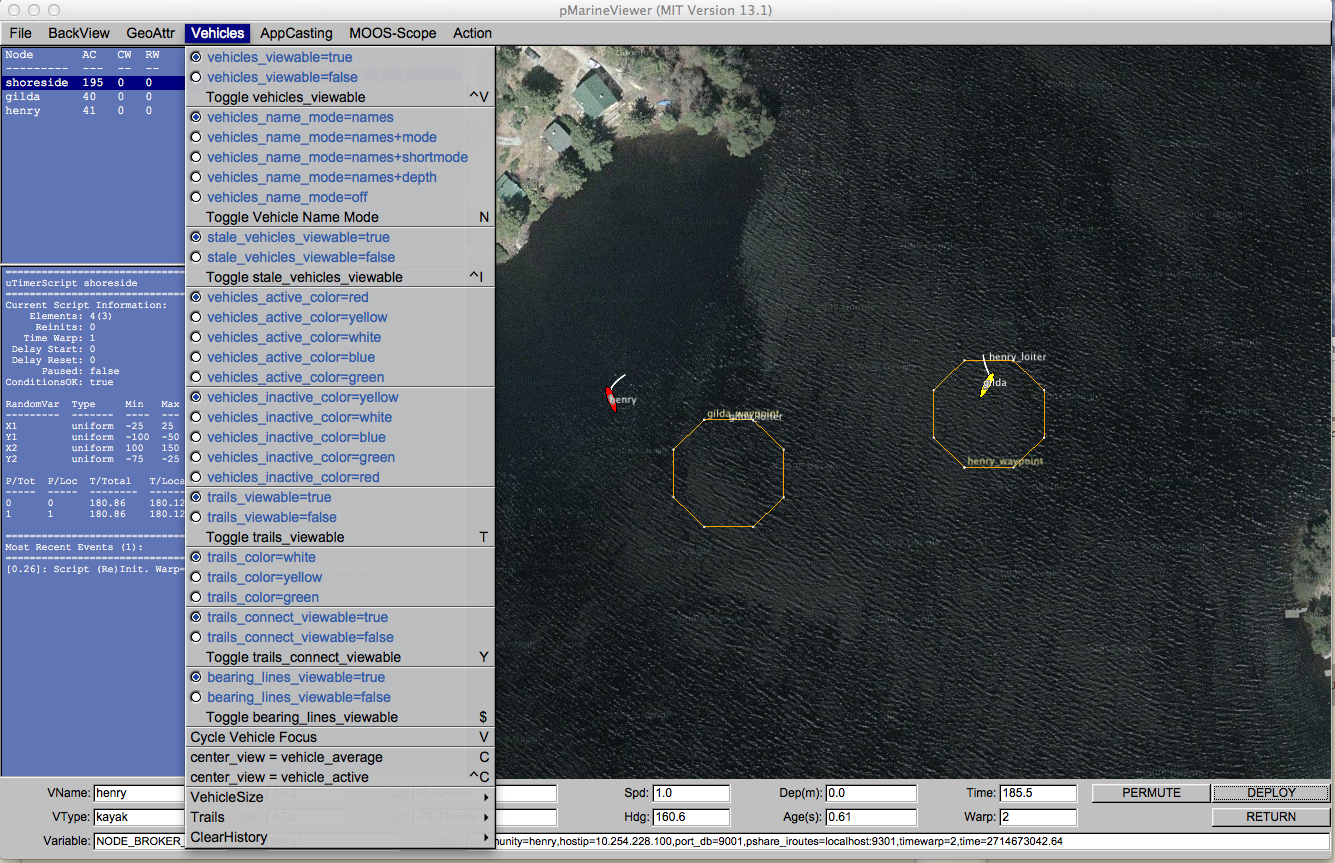
Figure 49.15: The Vehicles menu: This pull-down menu lists the options, with hot-keys, for affecting rendering vehicles and vehicle track history.
49.5.1 The Vehicle Name Mode [top]
Each vehicle rendered in the viewer has an optional label rendered with it. This label may be rendered in one of five modes:
- names: Just the vehicle name is rendered.
- names+mode: The vehicle name and the full helm mode is rendered.
- names+shortmode: The vehicle name and the short helm mode is rendered.
- names+depth: The vehicle name and its current depth are rendered.
- off: No label is rendered.
The default is names+shortmode. The names, off and depth modes are self explanatory. The names+mode and names+shortmode involve information typically provided in vehicle node reports about the state of the IvP helm. The helm uses hierarchical mode declarations as a way of configuring behaviors for missions. The helm mode for example be described with string looking something like "MODE@ACTIVE:LOITERING". In pMarineViewer the text next to the vehicle would be either this whole string if configured with the names+mode setting, or just "LOITERING" if configured with the names+shortmode setting.
The color of the rendered text may be changed from the default of white to any color in Appendix 88 with the vehicles_name_color configuration parameter.
49.5.2 Dealing with Stale Vehicles [top]
A stale vehicle is one who has not been heard from for a some time, perhaps because the vehicle is disabled, out of range, or recovered from the field. These vehicles can be a distraction. Their history may be outright cleared as described in Section 49.5.6 , but this requires action by the user or a posting to the MOOSDB.
Stale vehicles are also automatically dealt with by pMarineViewer in another way. After some number of seconds (30 by default), the vehicle label indicates the staleness. The label may look something like "henry (Stale Report: 231)" where the number indicates the number of seconds since the last node report received for this vehicle. After another period of time (30 by default), the vehicle may no longer rendered and removed from the appcasting pane.
A few features of this policy are configurable through the mission configuration file. The duration of time after which a vehicle is reported as stale may be changed from its default of 30 seconds with the stale_report_thresh parameter. The duration of time after which a vehicle is removed may be changed from its default of 30 seconds with the stale_remove_thresh parameter.
Stale vehicles are handled a bit differently when running in simulation and when running vehicles in the field. The difference between the two is determined by the MOOS time warp. Although it's possible to simulate with a time warp of one, here a time warp of one is interpreted as running physical vehicles. Simulated vehicles will be automatically removed from the viewer after stale_report_thresh + stale_remove_thresh seconds. When running actual vehicles, stale vehicles must be explicitly removed using the alt+'k' key to remove all stale vehicles, or ctrl+'k' key to remove the currently selected vehicle in the appcast pane.
49.5.3 Supported Vehicle Shapes [top]
The shape rendered for a particular vehicle depends on the type of vehicle indicated in the node report received in pMarineViewer. There are four types that are currently handled, an AUV shape, a glider shape, a kayak shape, and a ship shape, shown in Figure 49.16 .
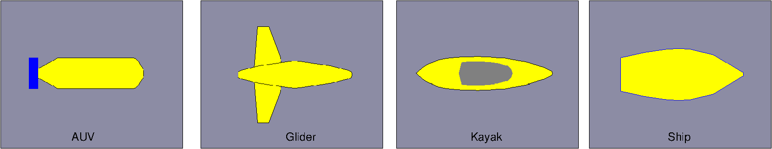
Figure 49.16: Vehicles: Types of vehicle shapes supported by pMarineViewer.
The default shape for an unknown vehicle type is currently set to be the shape "ship".
49.5.4 Vehicle Colors [top]
Vehicles are rendered in one of two colors, the active vehicle color and the inactive vehicle color. The active vehicle is the one who's data is being rendered in the data fields at the bottom of the pMarineViewer window, and who's name is in the VName: field. The active vehicle may be changed by selecting "Cycle Vehicle Focus" from the Vehicles pull-down menu, or toggling through with the 'v' key. The default color for the active vehicle is red, and the default for the inactive vehicle is yellow. These can be changed via the pull-down menu, or with the following parameters in the configuration file:
   vehicles_active_color   = <color>    // default is red
   vehicles_inactive_color = <color>    // default is yellow
The parameters and colors are case insensitive. All colors of the form described in Appendix 88 are acceptable.
49.5.5 Centering the Image According to Vehicle Positions [top]
The center_view menu items alters the center of the view screen to be panned to either the position of the active vehicle, or the position representing the average of all vehicle positions. Once the user has selected this, this mode remains sticky, that is the viewer will automatically pan as new vehicle information arrives such that the view center remains with the active vehicle or the vehicle average position. As soon as the user pans manually (with the arrow keys), the viewer breaks from trying to update the view position in relation to received vehicle position information. The rendering of the vehicles can made larger with the '+' key, and smaller with the '-' key, as part of the VehicleSize pull-down menu as shown. The size change is applied to all vehicles equally as a scalar multiplier. Currently there is no capability to set the vehicle size individually, or to set the size automatically to scale.
49.5.6 Vehicle Trails [top]
Vehicle trail (track history) rendering can be toggled off and on with the 't' key. The default is on. The startup default setting may be changed to off in the mission configuration file with trails_viewable=false.
Trail Color and Point Size [top]
The trail color by default is white. A few other colors are available in the Vehicles pull-down menu. A color may also be chosen in the mission configuration file with trail_color=<color> using any color listed in Appendix 88 . The trail point size may range from [1,10]. The default setting is 2. The size may be changed at runtime by the Vehicles/Trails pull-down menu, or with the '{' and '\'} hot keys. The startup trail size may also be set in the mission configuration file with trails_point_size=<int> parameter.
Trail Length and Connectivity [top]
Trails have a fixed-length history by default of 100 points. This may be changed via the Vehicles/Trails pull-down menu, or with the hot keys '(' and ')'. The startup default length may also be set in the mission configuration file with trails_length=<int> with values in range of [0, 10000].
Individual trail points can be rendered with a line connecting each point, or by just showing the points. When the node report stream is flowing quickly, typically the user doesn't need or want to connect the points. When the viewer is accepting input from an AUV with perhaps a minute or longer delay in between reports, the connecting of points is helpful. This setting can be toggled with the 'y' or key, with the default being off. The startup default may be set to on with the mission file paramter trails_connect_viewable=true.
Resetting or Clearing the Trails [top]
A vehicle's history sometimes needs to be cleared, for example when a vehicle has not been heard from in a long time, or has been recovered. Its trails and other geometric objects posted to the viewer can become a distraction. This may be done in a couple ways. First via the Action pull-down menu, the last menu item allows the user to clear the history of all vehicles or a selected vehicle. The Ctrl-9 hot key can be used to clear all vehicle histories. A select vehicle history may also be cleared by posting to the MOOS variable TRAIL_RESET with the name of the vehicle.
49.6 The AppCast Pull-Down Menu [top]
With the addition of appcasting to MOOS, pMarineViewer has been augmented to serve as an appcast viewer (along with the other appcast viewer tools, uMAC, and uMACView). The motivation for appcasting and how to build appcast enabled MOOS applications are discussed elsewhere in Section 73 . The focus here is on the AppCast menu items and their effect on rendering to the user.
49.6.1 Turning On and Off AppCast Viewing [top]
The AppCast pull-down menu, shown in Figure 49.17 allows adjustments to be made to the appcast rendering. The very first set of menu options allows the user to control whether the set of appcasting panes is viewed or not. The first two menu items allow the explicit on or off selection and also indicate the mission configuration parameter to turn appcast panes off by default, appcast_viewable=false. The third menu option allows the user to toggle the present setting and show that the 'a' key can be alternately used as shortcut for toggling.
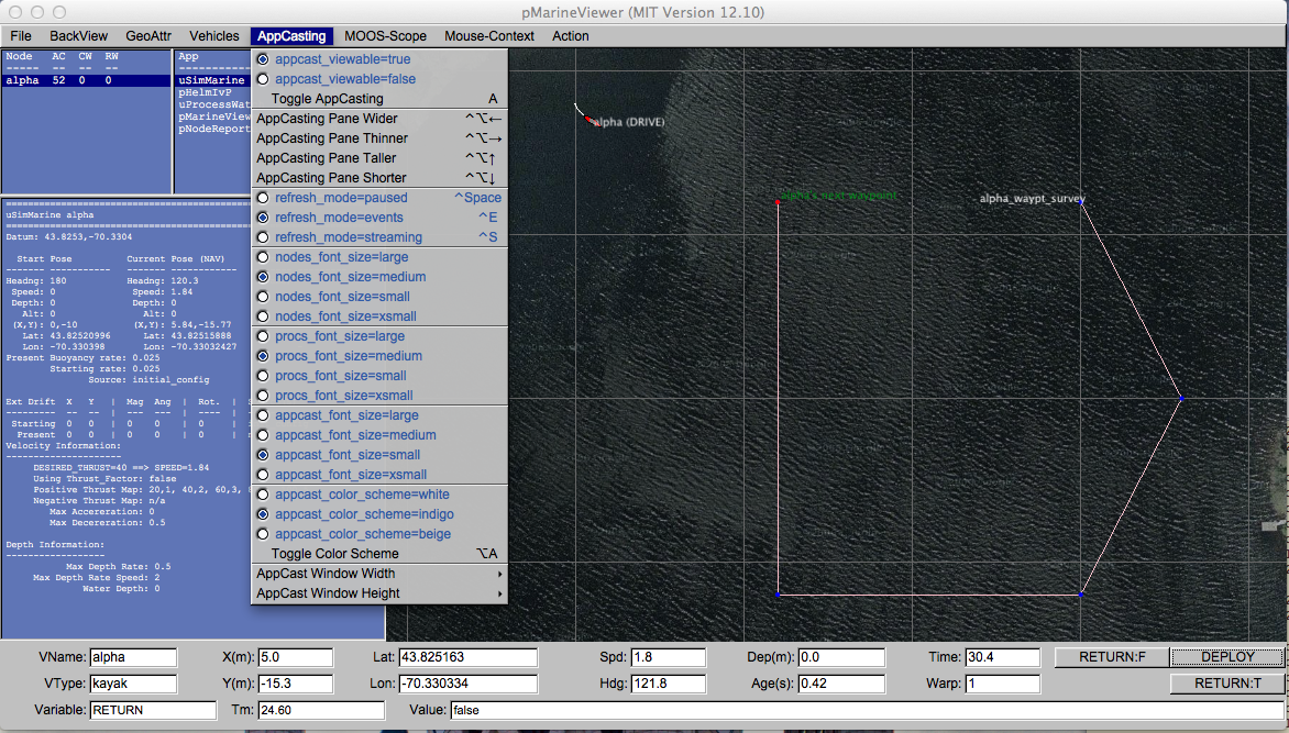
Figure 49.17: The AppCast menu: This pull-down menu lists the options, with hot-keys, for affecting rendering aspects of the appcast panels, and policy for soliciting appcasts from known vehicles and applications.
49.6.2 Adjusting the AppCast Viewing Panes Height and Width [top]
The next set of menu items allow the relative size of the appcasting panes to be adjusted. The width of the three panes may be increased or decreased with the left and right arrow keys, and the height of the lower appcasting window relative to the two upper windows may be adjusted with the up and down arrow keys. In both cases, along with the arrow keys, the user must also hold down the Ctrl and Alt keys. Alternatively the Ctrl and Shift keys may be uses. Both modes are supported since user key bindings vary between users. The Alt + arrow keys are common in Ubuntu for switching work spaces for example.
The appcast pane extents may also be set to the user's liking in the mission configuration file with the parameters appcast_width and appcast_height. The allowable range of values for each may be seen by pulling down the "AppCast Window Width" and "AppCast Window Height" sub-menus of the AppCast pull-down menu.
49.6.3 Adjusting the AppCast Refresh Mode [top]
The appcast refresh mode refers to the policy of sending appcast requests to known vehicles and applications. This is discussed more fully in Section 74.4 , but summarized here. Appcasting apps are implemented to be lazy with respect to generating appcasts - they will not generate them unless asked. And even when asked, the request comes with an expiration after which, if no new request has been received, the application returns to the lazy mode of producing no appcasts. So, for pMarineViewer to function as an appcast viewer, under the hood it must be also generating appcast requests (APPCAST_REQ postings) to the MOOSDB. The refresh mode refers to this under-the-hood policy.
In the paused refresh mode, pMarineViewer is not generating any appcast requests at all. This is not the default and typically not very helpful, but it may be useful when the viewer is situated in the field with only a low-bandwidth connection to remote vehicles. The refresh mode may be set to paused via the pull-down menu selection, with the CTRL+Spacebar hot key, or set in the mission configuration file with refresh_mode=paused.
In the events refresh mode, the default mode, pMarineViewer is generating appcast requests only to the selected vehicle and the selected MOOS application. Even this is only partly true. In fact it is generating another kind of appcast request to all vehicles and apps, but this kind of request comes with the caveat that an app is only to generate an appcast report if a new run warning has been detected. Otherwise these apps remain lazy. In this mode you should expect to see regular appcasts received for the selected app, and updates for the other apps only if something worthy of a run warning has occurred. You can confirm this for yourself by looking at the counter reflecting the number of appcasts received for any application. This counter is under the AC column in the upper panes. The refresh mode may be set to events via the pull-down menu selection, with the CTRL+'e' hot key, or set in the mission configuration file with refresh_mode=events. The latter would be redundant however since this is the default mode.
In the streaming refresh mode, pMarineViewer is generating appcast requests to all vehicles and all apps to generate appcasts all the time. This mode is a bandwidth hog, but it may be useful at times, especially to debug why a particular application is silent. If it is not generating and appcast in this mode, then something may indeed be wrong. The refresh mode may be set to streaming via the pull-down menu selection, with the CTRL+'s' hot key, or set in the mission configuration file with refresh_mode=streaming.
49.6.4 Adjusting the AppCast Fonts [top]
The font size of the text in the appcasting panes may be adjusted. There are three panes:
- Nodes Pane: The upper left pane shows the list of nodes (typically synonymous with vehicles), presently known to the viewer.
- Procs Pane: The upper right pane show the list of apps, for the chosen node, presently known to the viewer.
- AppCast Pane: The bottom pane shows the contents of the presently selected appcast report.
For each pane the possible font settings are large, medium, small, and xsmall. The default for the upper panes is medium, and the default for the appcast pane is small. Font sizes may be changed via the pull-down menu or set to the user's liking in the mission configuration file with nodes_font_size, procs_font_size, and appcast_font_size parameters.
49.6.5 Adjusting the AppCast Color Scheme [top]
A few different color schemes governing the three appcast panes are available. The default color scheme is "indigo", reflected in the Figure 49.17 for example. The other two color schemes are "white" and "beige". The color scheme may be changed via the pull-down menu, toggled with the ALT+'a' hot key, or set to the user's liking in the mission configuration file with appcast_color_scheme parameter.
49.7 The MOOS-Scope Pull-Down Menu [top]
The MOOS-Scope pull-down menu allows the user to configure pMarineViewer to scope on one or more variables in the MOOSDB. The viewer allows visual scoping on only a single variable at a time, but the user can select different variables via the pull-down menu, or toggle between the current and previous variable with the '/' key, or cycle between all registered variables with the CTRL+'/' key. The scope fields are on the bottom of the viewer as shown in Figure 49.18 .
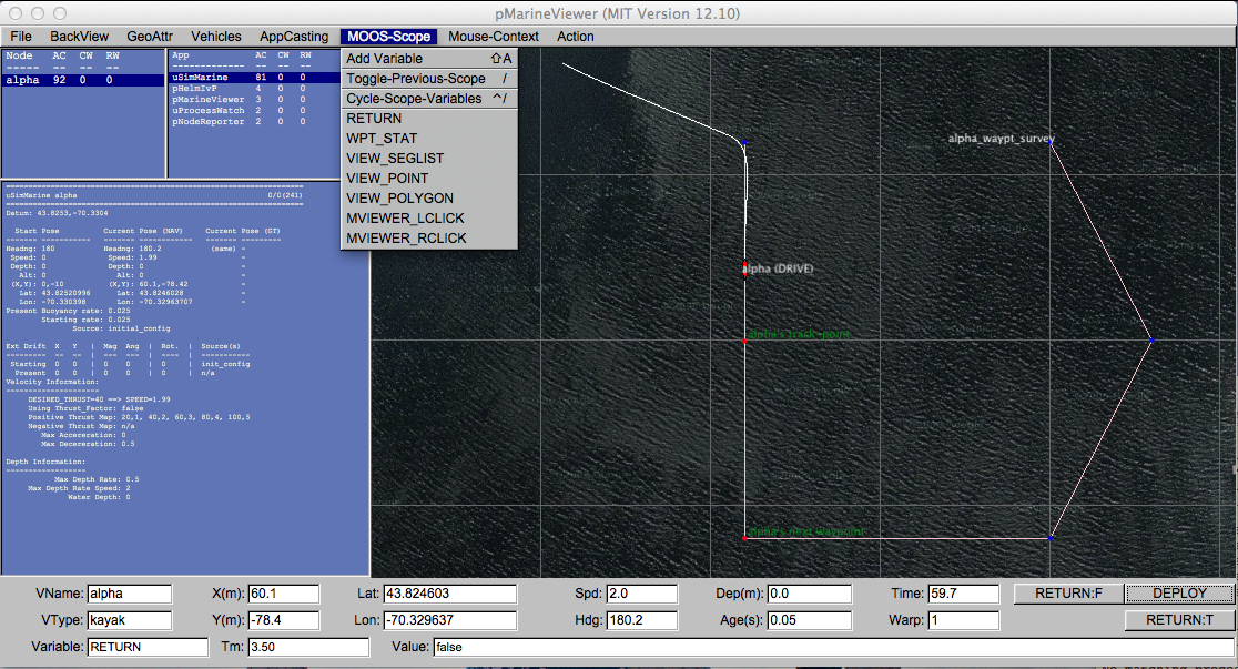
Figure 49.18: The Scope Menu: This pull-down menu allows the user to adjust which pre-configured MOOS variable is to be scoped, or to add a new variable to the scope list.
The three fields show (a) the variable name, (b) the last time is was updated, and (c) the current value of the variable. Configuration of the menu is done in the MOOS configuration block with entries similar to the following (which correlate to the particular items in the pull-down menu in Figure 49.18 ):
     scope = RETURN, WPT_STAT, VIEW_SEGLIST, VIEW_POINT, VIEW_POLYGON
     scope = MVIEWER_LCLICK, MVIEWER_RCLICK
The keyword scope is not case sensitive, but the MOOS variables are. If no entries are provided in the MOOS configuration block, the pull-down menu contains a single item, the "Add Variable" item. By selecting this, the user will be prompted to add a new MOOS variable to the scope list. This variable will then immediately become the actively scoped variable, and is added to the pull-down menu.
49.8 The Action Pull-Down Menu [top]
The Action pull-down menu allows the user to invoke pre-define pokes to the MOOSDB (the MOOSDB to which the pMarineViewer is connected). While hooks for a limited number of pokes are available by configuring on-screen buttons (Section 49.2.3 ), the number of buttons is limited to four. The "Action" pull-down menu allows for as many entries as will reasonably be shown on the screen. Each action, or poke, is given by a variable-value pair, and an optional grouping key. Configuration is done in the MOOS configuration block with entries of the following form:
action = menu_key=<key> # <MOOSVar>=<value> # <MOOSVar>=<value> # ...
If no such entries are provided, this pull-down menu will not appear. The fields to the right of the action are separated by the '#' character for convenience to allow several entries on one line. If one wants to use the '#' character in one of the variable values, putting double-quotes around the value will suffice to treat the '#' character as part of the value and not the separator. If the pair has the key word menu_key on the left, the value on the right is a key associated with all variable-value pairs on the line. When a menu selection is chosen that contains a key, then all variable-value pairs with that key are posted to the MOOSDB. The following configuration will result in the pull-down menu depicted in Figure 49.19 .
     action  = menu_key=deploy # DEPLOY = true # RETURN = false
     action+ = menu_key=deploy # MOOS_MANUAL_OVERIDE=false
     action  = RETURN=true
The action+ variant hints to the viewer that a line should be rendered in the pull-down menu separating it from following items.
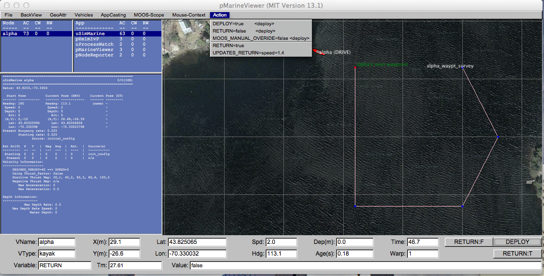
Figure 49.19: The Action menu: The variable value pairs on each menu item may be selected for poking or writing the MOOSDB. The three variable-value pairs above the menu divider will be poked in unison when any of the three are chosen, because they were configured with the same key, <deploy>, shown to the right on each item.
The variable-value pair being poked on an action selection will determine the variable type by the following rule of thumb. If the value is non-numerical, e.g., true, one, it is poked as a string. If it is numerical it is poked as a double value. If one really wants to poke a string of a numerical nature, the addition of quotes around the value will suffice to ensure it will be poked as a string. For example:
action = Vehicle=Nomar # ID="7"
As with any other publication to the MOOSDB, if a variable has been previously posted with one type, subsequent posts of a different type will be ignored.
49.9 The Mouse-Context Pull-Down Menu [top]
The Mouse-Context pull-down menu is an optional menu - it will not appear unless it is configured for use. It is used for changing the context of left and right mouse clicks on the operation area.
49.9.1 Generic Poking of the MOOSDB with the Operation Area Position [top]
When the user clicks the left or right mouse in the geo portion of the pMarineViewer window, the variables MVIEWER_LCLICK and MVIEWER_RCLICK are published respectively with the operation area location of the mouse click, and the name of the active vehicle. A left mouse click may result in a publication similar to:
MVIEWER_LCLICK = x=19.0,y=57.0,lat=43.8248027,lon=-70.3290334,vname=henry,counter=1
A counter is maintained by pMarineViewer and is incremented and included on each post. The above style posting presents a generic way to convey to other MOOS applications an operation area position. In this case the other MOOS applications need to conform to this generic output. But, with a bit of further configuration, a similar custom post to the MOOSDB is possible to shift the burden of conformity away from the other MOOS applications where typically a user does not have the ability to change the interface.
49.9.2 Custom Poking of the MOOSDB with the Operation Area Position [top]
Custom configuration of mouse clicks is possible by (a) allowing the MOOS variable and value to be defined by the user, and (b) exposing a few macros in the custom specification to embed operation area information. Configuration is done in the MOOS configuration block with entries of the following form:
    left_context[<key>]  = <var-data-pair>
    right_context[<key>] = <var-data-pair>
The left_context and right_context keywords are case insensitive. If no entries are provided, this pull-down menu will not appear. The <key> component is optional and allows for groups of variable-data pairs with the same key to be posted together with the same mouse click. This is the selectable context in the Mouse-Context pull-down menu. If the <key> is empty, the defined posting will be made on all mouse clicks regardless of the grouping, as is the case with MVIEWER_LCLICK and MVIEWER_RCLICK.
Macros may be embedded in the string to allow the string to contain information on where the user clicked in the operation area. These patterns are: $(XPOS) and $(YPOS) for the local x and y position respectively, and $(LAT), and $(LON) for the latitude and longitude positions. The pattern $(IX) will expand to an index (beginning with zero by default) that is incremented each time a click/poke is made. This index can be configured to start with any desired index with the lclick_ix_start and rclick_ix_start configuration parameters for the left and right mouse clicks respectively. The following configuration will result in the pull-down menu depicted in Figure 49.20 .
    left_context[surface_point] = SPOINT = $(XPOS),$(YPOS)
    left_context[surface_point] = COME_TO_SURFACE = true
    left_context[return_point]  = RETURN_POINT = point=$(XPOS),$(YPOS), vname=$(VNAME)
    left_context[return_point]  = RETURN_HOME = true
    left_context[return_point]  = RETURN_HOME_INDEX = $(IX)
    right_context[loiter_point] = LOITER_POINT = lat=$(LAT), lon=$(LON)
    right_context[loiter_point] = LOITER_MODE = true
Note in the figure that the first menu option is "no-action" which shuts off all MOOS pokes associated with any defined groups (keys). In this mode, the MVIEWER_LCLICK and MVIEWER_RCLICK pokes will still be made, along with any other poke configured without a <key>.
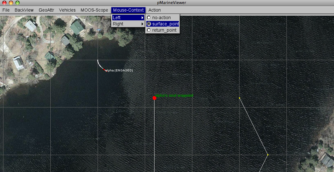
Figure 49.20: The Mouse-Context menu: Keywords selected from this menu will determine which groups of MOOS variables will be poked to the MOOSDB on left or mouse clicks. The variable values may have information embedded indicating the position of the mouse in the operation area at the time of the click.
49.10 Configuring and Using the Commander Pop-Up Window [top]
The commander pop-up window is meant to provide an extendable command and control interface for missions requiring more than a few on-screen buttons. It needs to be configured and thought through prior to mission launch, to reflect whatever the mission operator may need to do during the mission. The window conveniently pops up and is hidden by toggling the space bar. An example is shown below.
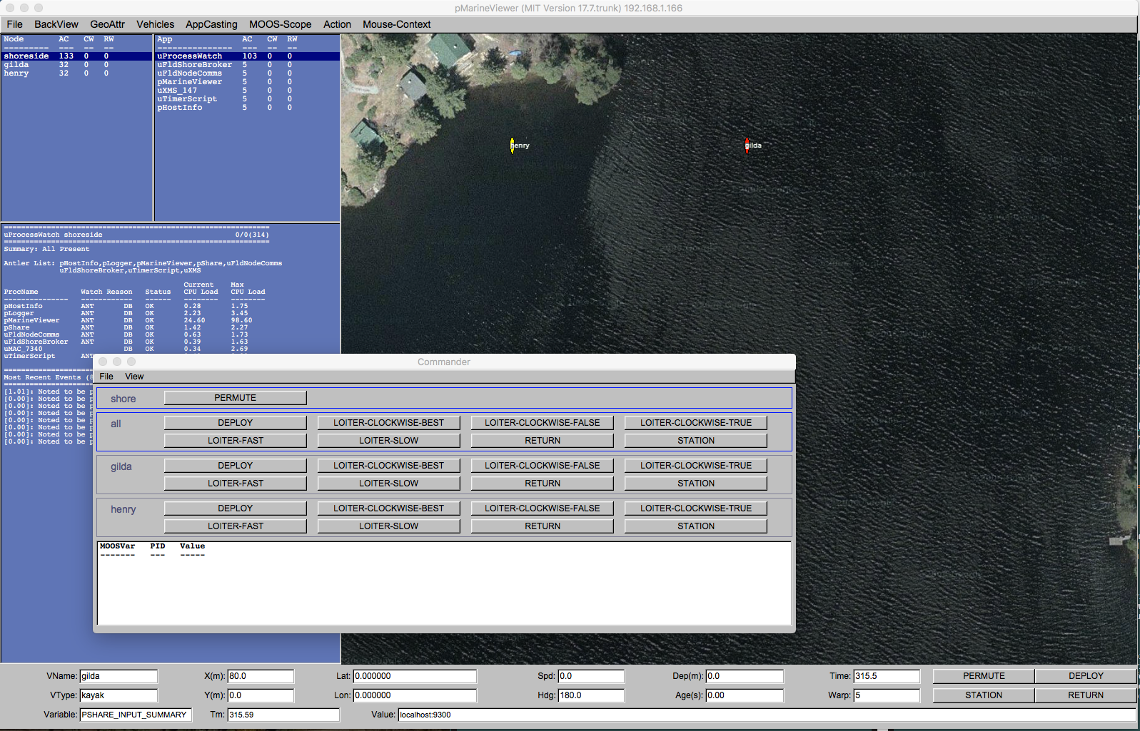
Figure 49.21: The commander pop-up window is toggled open/closed with the space-bar key and presents the user with a set of user-configured commands to either the all vehicles, individual vehicles, or the the pMarineViewer shoreside community itself.
Below we discuss how to work with the window and its content, how to configure the pop-up window, and the related assuptions of configuration in uFldShoreBroker to ensure proper command out to the vehicles.
49.10.1 Commander Pop-Up Window Actions and Content [top]
The commander pop-up window has typically four components as indicated in Figure 49.22 . The first component contains a single pane of buttons with postings to the local shoreside MOOSDB, not intended to be passed on to any vehicles. The second component contains a single pane of buttons for postings intended to be sent to all vehicles. The third component holds a dedicated pane for each known vehicle, with buttons intended for direct communication to the named vehicle. The fourth component contains the command history, a list of the actual postings made from recent button clicks, with the most recent postings at top.
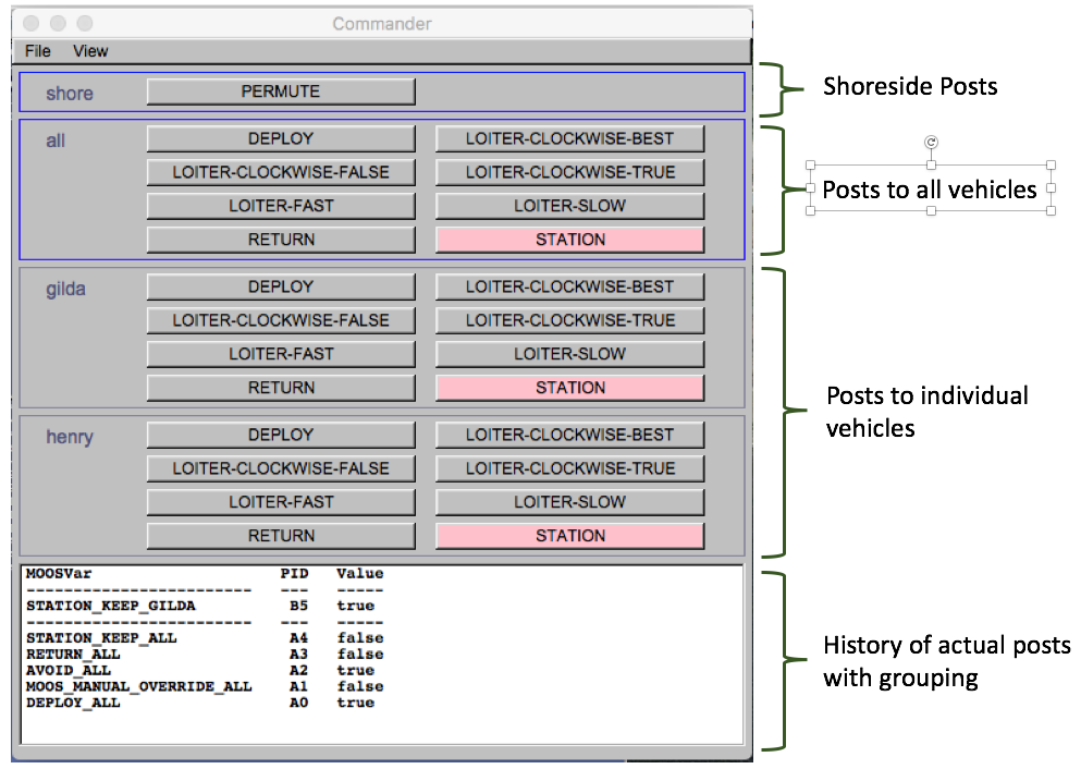
Figure 49.22: The commander pop-up window is contains four parts as shown. The button grouping is done automatically depending on the user configuration. Each button may be configured to make one or more posts to the MOOSDB.
The command history also indictes the clustering of posts associated with recent button clicks. The Post-ID, is shown in the middle column. All postings from the same button click, begin with the same letter, allowing the user to discern the group of postings resulting from a single button click. The user may also may a hypothetical post by clicking any button with the shift-key held down. In this case, no post will be made to the MOOSDB, but the actions that would have been posted are added to the command history, separated by a dashed line as in Figure 49.22 . A subsequent actual button click would erase he hypothetical lines from the command history. Finally, if screen real estate is an issue, the command history pane may be hidden by toggling with the 'p' character.
The position and sizing of the command-popup window may be adjusted upon opening, with the buttons retaining their size, but the button positions automatically adjusted to best fit the size of the window. As the user adjusts wider, the number of buttons in each row will grow, and the height will be as high as needed to fit the content. As the user adjusts taller, the command history pane is grown to show more history. The whole command pop-up window may be hidden and re-shown by toggling the spacebar-key. When doing so, note that not only the shape, but also the position w.r.t. the pMarineViewer window is also retained.
49.10.2 Commander Pop-Up Configuration [top]
The set of possible command buttons and their corresponding posts to the MOOSDB may be referred to as a command portfolio, or commandfolio for short. This configuration is achieved with a set of lines of the following format:
cmd = label=<val>, var<val>, sval=<val>, dval=<val>, receivers=<val>, color=<val>
The label field:
The button label is the text that will appear on the viewer button. It is also used as a unique identifier to associate several configuration lines together to make several posts with a single button.
The var field:
The var field names a single MOOS variable to be used in a post when this button is clicked. As such it should follow MOOS conventions and be upper case, no white space, not begin with a number, no use of special characters like '@', '?', '(' etc., and use the underscore character '_' to separae components. These are only conventions and not enforced.
The sval field:
If a posting is to be made with a string value, the sval field should be used to specify this value.
The dval field:
If a posting is to be made with a numerical (double) value, the dval field should be used to specify this value.
The receivers field:
This field specifies a colon-separated list of vehicles, e.g., henry:gilda to be receivers of the posts associated with this button. If, for example, a vehicle named henry is named, with the MOOS variable DEPLOY, a button click will result in a posting to the variable DEPLOY_HENRY. Two special names are reserved, "all" and "shorside". If "all" is used, DEPLOY_ALL will be posted, not DEPLOY_GILDA and DEPLOY_HENRY for example. If "shoreside" is used, simply DEPLOY will be posted.
The colors field:
If the user desires a certain command button to visually stand out, a color may be specified. For example, in Figure 49.22 , the button to order a vehicle to station keep is highlighted in red, since this is often regarded as the go-to action when or if a surface vehicle encounters intervention from an operator.
49.10.3 Commander Pop-Up Example Configuration from m2_berta Mission [top]
Below is an example commander pop-up window configuration from the m2_berta mission. It will result in the commander window shown in Figure 49.22 . Note the macro $(VNAMES) in many of the configuration lines. This macro is filled in at launch time by the colon-separated list of all vehicles being launched. See the launch script in the m2_berta mission for an example.
  cmd = label=DEPLOY, var=DEPLOY,  sval=true,  receivers=all:$(VNAMES)
  cmd = label=DEPLOY, var=MOOS_MANUAL_OVERRIDE,  sval=false,  receivers=all:$(VNAMES)
  cmd = label=DEPLOY, var=AVOID,  sval=true,  receivers=all:$(VNAMES)
  cmd = label=DEPLOY, var=RETURN,  sval=false,  receivers=all:$(VNAMES)
  cmd = label=DEPLOY, var=STATION_KEEP,  sval=false,  receivers=all:$(VNAMES)

  cmd = label=RETURN, var=RETURN, sval=true, receivers=all:$(VNAMES)
  cmd = label=RETURN, var=STATION_KEEP, sval=false, receivers=all:$(VNAMES)

  cmd = label=PERMUTE, var=UTS_FORWARD,  dval=0,  receivers=shore

  cmd = label=STATION, var=STATION_KEEP,  sval=true,  receivers=all:$(VNAMES), color=pink

  cmd = label=LOITER-FAST, var=UP_LOITER,  sval=speed=2.8,  receivers=all:$(VNAMES)
  cmd = label=LOITER-SLOW, var=UP_LOITER,  sval=speed=1.4,  receivers=all:$(VNAMES)

  cmd = label=LOITER-CLOCKWISE-TRUE,  var=UP_LOITER, sval=clockwise=true,  receivers=all:$(VNAMES)
  cmd = label=LOITER-CLOCKWISE-FALSE, var=UP_LOITER, sval=clockwise=false, receivers=all:$(VNAMES)
  cmd = label=LOITER-CLOCKWISE-BEST,  var=UP_LOITER, sval=clockwise=false, receivers=all:$(VNAMES)
49.10.4 Commander Pop-Up Coordination with pShare and uFldShoreBroker [top]
Neither the commander popup window, nor pMarineViewer for that matter, are able to communicate with vehicles directly. The convention here is that if posting such as DEPLOY=true is desired to be sent to say vehicle "henry", then a post of DEPLOY_HENRY=true is made instead. And if all vehicles are to be deployed with a single button click, then a posting of DEPLOY_ALL=true is made.
The assumption is made that an inter-MOOSDB share arrangement of some form, typically with pShare, is made from the shoreside community to each vehicle. This can be made directly with pShare with a pair of lines as the following:
   Output = src_name=DEPLOY_ALL, dest_name=DEPLOY, route=192.168.1.12:9300
   Output = src_name=DEPLOY_GUS, dest_name=DEPLOY, route=192.168.1.12:9300
The above pair of lines would be needed for each vehicle command, for each vehicle. This is accomplished much more conveniently if the uField Toolbox tool uFldShoreBroker is used to automatically coordinate known vehicles, and commands with pShare. The above pair of lines is instead:
qbridge = DEPLOY
And for multiple commands, with say five vehicles for example:
qbridge = DEPLOY, RETURN, STATION_KEEP, UP_LOITER, MOOS_MANUAL_OVERRIDE
This single line using uFldShoreBroker would require 30 separate pShare lines.
49.11 Configuration Parameters for pMarineViewer [top]
The blue items in pull-down menus are also available as mission file configuration parameters. The configuration parameter is identical to the pull-down menu text. For example in the BackView menu shown in Figure 49.7 , the menu item full_screen=true may also be set in the pMarineViewer configuration block verbatim with full_screen=true.
49.11.1 Configuration Parameters for the BackView Menu [top]
The parameters in Listing 49.2 relate to the BackView menu described more fully in Section 49.3 . Parameters in blue below correlate to parameters in blue in the pull-down menu. For these parameters, the text in the pull-down menu is identical to a similar entry in the configuration file.
Listing 49.2 - Configuration Parameters for pMarineViewer BackView Menu.
| back_shade: | Shade of gray background when no image is used. Legal value range: [0, 1]. Zero is black, one is white. |
| full_screen: | If true, viewer is in full screen mode (no appcasts, no fields rendered at the bottom). Legal values: true, false. Section 49.3.4 . |
| hash_delta: | Sets the hash line spacing. Legal values: 50, 100, 200, 500, 1000. The default is 100. Section 49.3.3 . |
| hash_shade: | Shade of hash marks. Legal value range: [0, 1]. Zero is black, one is white. Section 49.3.3 . |
| hash_viewable: | If true, hash lines are rendered over the op area. Legal values: true, false. The default is false. Section 49.3.3 . |
| log_the_image: | If true, a request is posted to pLogger to log a copy of the image and info file. Legal values: true, false. The default is false. Section 49.3.2 . |
| tiff_file: | Filename of a tiff file background image. Section 49.3.2 . |
| tiff_file_b: | Filename of another tiff file background image. Section 49.3.2 . |
| tiff_type: | Use the first tiff image if set to true. Legal values: true, false. The default is true. Section 49.3.2 . |
| tiff_viewable: | Use the tiff background image if set to true. Otherwise a gray screen is used as a background. Legal values: true, false. The default it true. Section 49.3.2 . |
| view_center: | Sets the center of the viewing image in x,y local coordinates. Legal values: (double,double). The default is (0,0). |
49.11.2 Configuration Parameters for the GeoAttributes Menu [top]
The parameters in Listing 49.3 relate to the GeoAttributes pull-down menu described more fully in Section 49.4 . Parameters in blue below correlate to parameters in blue in the pull-down menu. For these parameters, the text in the pull-down menu is identical to a similar entry in the configuration file.
Listing 49.3 - Configuration Parameters for pMarineViewer Geometry Menu.
| circle_viewable_all: | If false, circles are suppressed from rendering. Legal values: true, false. The default is true. Section 49.4.1 . |
| circle_viewable_labels: | If false, circle labels are suppressed from rendering. Legal values: true, false. The default is true. Section 49.4.1 . |
| comms_pulse_viewable_all: | If false, comms pulses are suppressed from rendering. Legal values: true, false. The default is true. Section 49.4.5 . |
| datum_viewable: | If false, the datum is suppressed from rendering. Legal values: true, false. The default is true. Sections 49.3.2 and 49.4 . |
| datum_color: | The color used for rendering the datum. Legal values: Any color listed in the Colors Appendix. The default is red. Sections 49.3.2 and 49.4 . |
| datum_size: | The size of the point used to render the datum. Legal values: Integers in the range [1, 10]. The default is 2. Sections 49.3.2 and 49.4 . |
| drop_point_viewable_all: | If false, drop points are suppressed from rendering. Legal values: true, false. The default is true. Section 49.4.7 . |
| drop_point_coords: | Specifies whether the drop point labels are in earth or local coordinates. Legal values are: as-dropped, lat-lon, local-grid. The default is as-dropped. Section 49.4.7 . |
| drop_point_vertex_size: | The size of the point used to render a drop point. Legal values: Integers in the range [1, 10]. The default is 2. Section 49.4.7 . |
| grid_viewable_all: | If false, grids are suppressed from rendering. Legal values: true, false. The default is true. |
| grid_viewable_labels: | If false, grid labels are suppressed from rendering. Legal values: true, false. The default is true. |
| grid_viewable_opaqueness: | The degree to which grid renderings are opaque. Legal range: [0, 1]. The default is 0.3. |
| marker | A marker may be stated in the configuration file with the same format of the VIEW_MARKER message. Section 49.4.4 . |
| marker_scale: | The scale applied to marker renderings. Legal range: [0.1, 100]. The default is 1.0. Section 49.4.4 . |
| marker_viewable_all: | If false, markers are suppressed from rendering. Legal values: true, false. The default is true. Section 49.4.4 . |
| marker_edge_width: | Markers are rendered with an outer black edge. The edge may be set thicker to aid in viewing. Legal values: Integer values in the range [1, 10]. The default is 1. Section 49.4.4 . |
| marker_viewable_labels: | If false, marker labels are suppressed from rendering. Legal values: true, false. The default is true. Section 49.4.4 . |
| oparea_viewable_all: | If false, oparea lines are suppressed from rendering. Legal values: true, false. The default is true. |
| oparea_viewable_labels: | If false, oparea label is suppressed from rendering. Legal values: true, false. The default is true. |
| point_viewable_all: | If false, points are suppressed from rendering. Legal values: true, false. The default is true. Section 49.4.1 . |
| point_viewable_labels: | If false, point labels are suppressed from rendering. Legal values: true, false. The default is true. Section 49.4.1 . |
| polygon_viewable_all: | If false, polygons are suppressed from rendering. Legal values: true, false. The default is true. Section 49.4.1 . |
| polygon_viewable_labels: | If false, polygon labels are suppressed from rendering. Legal values: true, false. The default is true. Section 49.4.1 . |
| range_pulse_viewable_all: | If false, range pulses are suppressed from rendering. Legal values: true, false. The default is true. Section 49.4.5 . |
| seglist_viewable_all: | If false, seglists are suppressed from rendering. Legal values: true, false. The default is true. Section 49.4.1 . |
| seglist_viewable_labels: | If false, seglist labels are suppressed from rendering. Legal values: true, false. The default is true. Section 49.4.1 . |
| vector_viewable_all: | If false, vectors are suppressed from rendering. Legal values: true, false. The default is true. Section 49.4.1 . |
| vector_viewable_labels: | If false, vector labels are suppressed from rendering. Legal values: true, false. The default is true. Section 49.4.1 . |
49.11.3 Configuration Parameters for the Vehicles Menu [top]
The parameters in Listing 49.4 relate to the Vehicles pull-down menu described more fully in Section 49.5 . Parameters in blue below correlate to parameters in blue in the pull-down menu. For these parameters, text in the pull-down menu is identical to a similar entry in the configuration file.
Listing 49.4 - Configuration Parameters for pMarineViewer Vehicles Pull-Down Menu.
| bearing_lines_viewable: | If false, bearing lines will be suppressed from rendering. Legal values: true, false. The default is true. |
| center_view: | Sets the pan position to be either directly above the active vehicle, or the average of all vehicles. Legal values: active, average. The default is neither, resulting in the pan position being set to either (0,0) or set via other configuration parameters. Section 49.5.5 . |
| stale_remove_thresh: | Number of seconds after a stale vehicle has been detetected before being removed. When time warp is one, vehicles are not automatically removed at all, and this number is meaningless. Legal values: Any non-negative number. The default is 30. Section 49.5.2 . |
| stale_report_thresh: | Number of seconds after which a vehicle report will be considered stale. Legal values: Any non-negative number. The default is 60. Section 49.5.2 . |
| trails_color: | The color of trail points rendered behind vehicles to indicate recent vehicle position history. Legal values: Any color listed in the Colors Appendix. The default is white. Section 49.5.6 . |
| trails_connect_viewable: | If true the vehicle trail points are each connected by a line. Useful when node reports have large gaps in time. Legal values: true, false. The default is true. Section 49.5.6 . |
| trails_length: | The number of points retained for the rendering of vehicle trails. Legal values: Integers in the range [1, 100000]. The default is 100. Section 49.5.6 . |
| trails_point_size: | The size of the points rendering the vehicle trails. Legal values: Integers in the range [1, 10]. The default is 1. Section 49.5.6 . |
| trails_viewable: | If false, vehicle trails are suppressed from rendering. Legal values: true, false. The default is true. Section 49.5.6 . |
| vehicles_active_color: | The color of the active vehicle (the one who's data is being shown in the bottom data fields). Legal values: Any color listed in the Colors Appendix. The default is red. Section 49.5.4 . |
| vehicles_inactive_color: | The color of inactive vehicles. Legal values: Any color listed in the Colors Appendix. The default is yellow. Section 49.5.4 . |
| vehicles_shape_scale: | The scale factor applied to vehicle size rendering. Legal values in the range: [0.1, 100]. The default is 1.0. Section 49.5.3 . |
| vehicles_name_mode: | Sets the mode for rendering the vehicle label. Legal values are: names, names+mode, names+shortmode, names+depth, off. The default is names+shortmode. Section 49.5.1 . |
| vehicles_name_color: | Sets the color for rendering the vehicle label. Legal values are any color in Appendix 88 . The default is white. Section 49.5.4 . |
| vehicles_viewable: | If false, vehicles are suppressed from rendering. Legal values: true, false. The default is true. Section 49.5 . |
49.11.4 Configuration Parameters for the AppCast Menu [top]
The parameters in Listing 49.5 relate to the AppCast pull-down menu described more fully in Section 49.6 . Parameters in blue below correlate to parameters in blue in the pull-down menu. For these parameters, text in the pull-down menu is identical to a similar entry in the configuration file.
Listing 49.5 - Configuration Parameters for pMarineViewer AppCast Pull-Down Menu.
| appcast_color_scheme: | The color scheme used in all three appcasting panes, affecting background color and font color. Legal values: white, indigo, beige. The default is indigo. Section 49.6.5 . |
| appcast_font_size: | The font size uses in the appcast pane of the set of appcasting panes. Legal values: large, medium, small, xsmall. The default is small. Section 49.6.4 . |
| appcast_height: | The height of the appcasting bottom pane as a percentage of the total pMarineViewer window height. Legal values: [30, 35, 40, 45,..., 85, 90]. The default is 75. Section 49.6.2 . |
| appcast_viewable: | If true, the appcasting set of panes are rendered on the left side of the viewer. Legal values: true, false. The default is true. Section 49.6.1 . |
| appcast_width: | The width of the appcasting panes as a percentage of the total pMarineViewer window width. Legal values: [20, 25, 30, 35,..., 65, 70]. The default is 30. Section 49.6.2 . |
| nodes_font_size: | the font size uses in the nodes pane of the set of appcasting panes. Legal values: large, medium, small, xsmall. The default is medium. Section 49.6.4 . |
| procs_font_size: | The font size uses in the procs pane of the set of appcasting panes. Legal values: large, medium, small, xsmall. The default is medium. Section 49.6.4 . |
| refresh_mode: | Determines the manner in which appcast requests are sent to apps. Legal values: paused, events, streaming. The default is events. Section 49.6.3 . |
49.11.5 Configuration Parameters for the Scope, MouseContext and Action Menus [top]
Listing 49.6 - Configuration Parameters the Scope, MouseContext and Action Menus.
| scope: | A comma separated list of MOOS variables to scope. Section 49.7 . |
| oparea: | A specification of the operation area boundary for optionally rendering. |
| button_one: | A configurable command and control button. Section 49.2.3 . |
| button_two: | A configurable command and control button. Section 49.2.3 . |
| button_three: | A configurable command and control button. Section 49.2.3 . |
| button_four: | A configurable command and control button. Section 49.2.3 . |
| action: | A MOOS variable-value pair for posting, available under the Action pull-down menu. Section 49.8 . |
| left_context: | Allows the custom configuration of left mouse click context. Section 49.9 . |
| right_context: | Allows the custom configuration of right mouse click context. Section 49.9 . |
| lclick_ix_start: | Starting index for the left mouse index macro. Section 49.9 . |
| rclick_ix_start: | Starting index for the right mouse index macro. Section 49.9 . |
49.12 Publications and Subscriptions for pMarineViewer [top]
The interface for pMarineViewer, in terms of publications and subscriptions, is described below. This same information may also be obtained from the terminal with:
$ pMarineViewer --interface or -i
49.12.1 Variables Published by pMarineViewer [top]
It is possible to configure pMarineViewer to poke the MOOSDB via either the Action pull-down menu (Section 49.8 ), or via configurable GUI buttons (Section 49.2.3 ). It may also publish to the MOOSDB variables configured to mouse clicks (Section 49.9 ). So the list of variables that pMarineViewer publishes is somewhat user dependent, but the following few variables may be published in all configurations.
- APPCAST: Contains an appcast report identical to the terminal output. Appcasts are posted only after an appcast request is received from an appcast viewing utility. Section 74.4 .
- APPCAST_REQ_<COMMUNITY>: As an appcast viewer, pMarineViewer also generates outgoing appcast requests to MOOS communities it is aware of, including its own MOOS community. These postings are typically bridged to the other named MOOS community with the variable renamed simply to APPCAST_REQ when it arrives in the other community.
- HELM_MAP_CLEAR: This variable is published once when the viewer connects to the MOOSDB. It is used in the pHelmIvP application to clear a local buffer used to prevent successive identical publications to its variables.
- PMV_CONNECT: This variable is published once when the viewer connects to the MOOSDB. It is always published with the value 0. It can be used by any application that would like to publish or republish visual artifacts ensuring that pMarineViewer receives all mail in a sequence. Otherwise if the viewer comes up after the sequences is published, it may only get the last element in the sequence.
- MVIEWER_LCLICK: When the user clicks the left mouse button, the position in local coordinates, along with the name of the active vehicle is reported. This can be used as a command and control hook as described in Section 49.9 .
- MVIEWER_RCLICK: This variable is published when the user clicks with the right mouse button. The same information is published as with the left click.
- MVIEWER_UNHANDLED_MAIL: If the viewer receives mail that it is unable to parse, info on the MOOS variable and its content will be posted in this variable for debugging.
- PLOGGER_CMD: This variable is published with a "COPY_FILE_REQUEST" to log a copy of the image and info file, only if log_the_image is set to true. Section 49.3.2 .
49.12.2 Variables Subscribed for by pMarineViewer [top]
- APPCAST: As an appcast viewer, pMarineViewer also subscribes for appcasts from other other applications and communities to provide the content for its own viewing capability.
- APPCAST_REQ: As an appcast enabled MOOS application, pMarineViewer also subscribes for appcast requests. Each incoming message is a request to generate and post a new appcast report, with reporting criteria, and expiration. Section 74.4 .
- NODE_REPORT: This is the primary variable consumed by pMarineViewer for collecting vehicle position information.
- NODE_REPORT_LOCAL: This serves the same purpose as the above variable. In some simulation cases this variable is used.
- PHI_HOST_INFO: A string representing the detected IP address, published by pHostInfo. Used for augmenting the pMarineViewer title bar with the current IP address.
- TRAIL_RESET: When the viewer receives this variable it will clear the history of trail points associated with each vehicle. This is used when the viewer is run with a simulator and the vehicle position is reset and the trails become discontinuous.
- VIEW_CIRCLE: A string representation of an XYCircle object.
- VIEW_COMMS_PULSE: A string representation of an XYCommsPulse object.
- VIEW_GRID: A string representation of a XYConvexGrids object.
- VIEW_GRID_CONFIG: A string representation of a XYGrid configuration.
- VIEW_GRID_DELTA: A string representation of a XYGrid configuration.
- VIEW_POINT: A string representation of an XYPoint object.
- VIEW_POLYGON: A string representation of an XYPolygon object.
- VIEW_SEGLIST: A string representation of an XYSegList object.
- VIEW_MARKER: A string designation of a marker type, size and location.
- VIEW_RANGE_PULSE: A string representation of an XYRangePulse object.
- VIEW_VECTOR: A string representation of an XYVector object
Page built from LaTeX source using the texwiki program.