The Muster Behavior
Maintained by: mikerb@mit.edu  Get PDF
src: project-pavlab/bhvdocs/bhv_muster
1 The Muster Behavior
2 The OnRunState() Loop
3 Generating the Voronoi Partition and Set Point
3.1 Obtaining Vehicle Positions
3.2 Voronoi Partitions
3.3 The Set Point and Muster Mode
4 Muster Modes and Capture Flags
4.1 Muster Modes and Configured Criteria
4.2 Muster Capture Flags
5 Auto Completion
5.1 Enabling Auto Completion
5.2 Sharing the Muster Mode to Other Vehicles
5.3 Checking for Completion
5.4 Muster Completion
6 Implemention of the Motion Policy
6.1 Application of the Muster Mode
6.2 Determining the Orientation to the Set Point
6.3 Construction of the IvP Objective Function
6.4 Active Participation of the Muster Behavior
7 Performance Metrics and Macros
7.1 Performance Metrics Related to the Voronoi Field
7.2 Performance Metrics Related to Odometry
7.3 Non Metrics Related Macros
7.4 Summary of all Macros
8 Supported Macros for the Muster Behavior
9 Configuring the Muster Behavior with Multiple Muster Regions
9.1 Configuration Parameters
1 The Muster Behavior
This behavior will drive the vehicle to a specified region, the muster region, given by a convex polygon. Upon arrival, it will use position information about local contacts also in the region, to adjust its own position based on a variation of Llyod's algorithm. This algororithm is based on a Voronoi decomposition of the muster region as shown below.

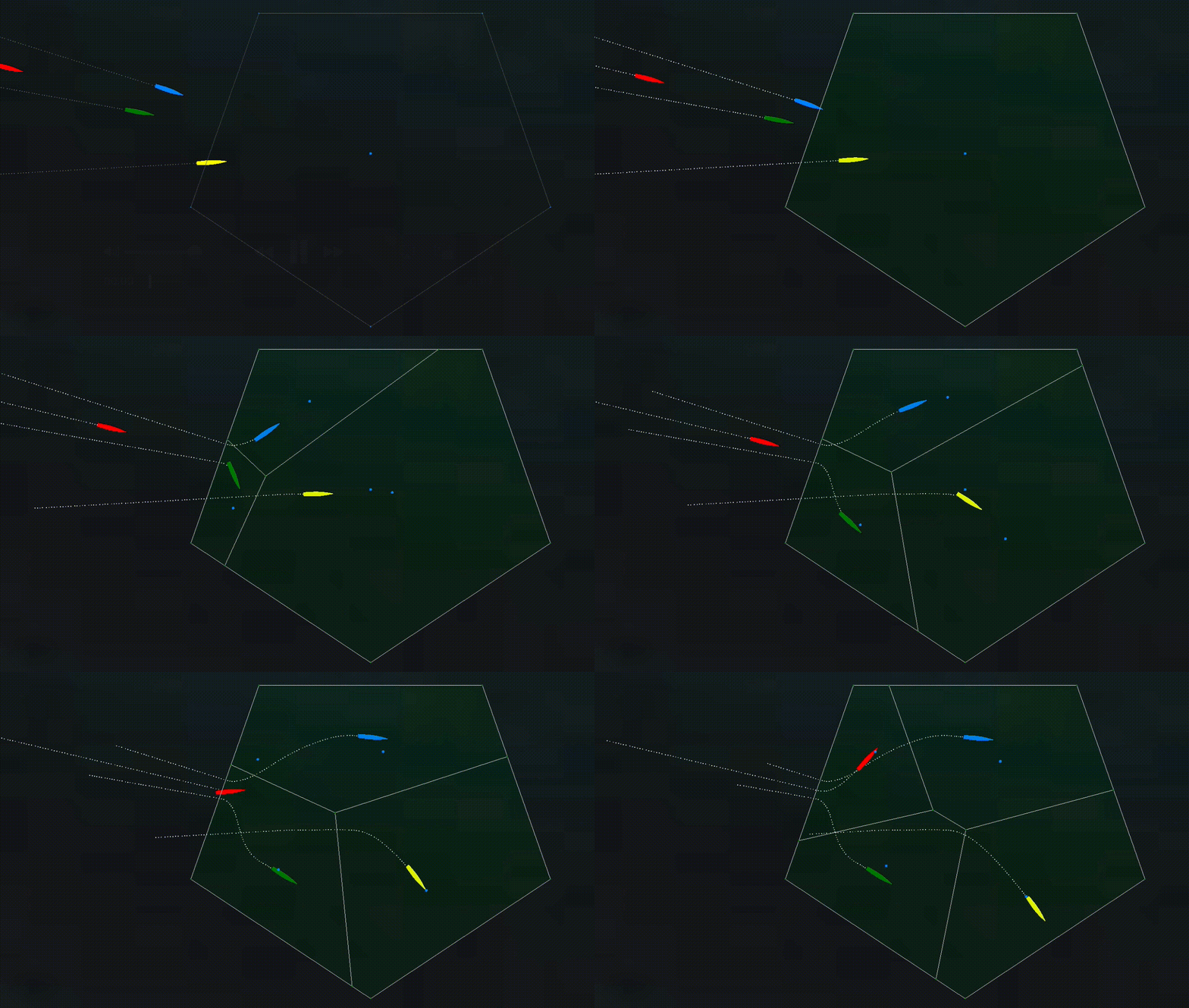
Figure 1.1: Four-vehicle Muster Four vehicles approach a muster region. As each vehicle enters the region the Voronoi decomposition is shown. When the first vehicle enters, there is only one region. When the second vehicle enters, there are two regions, and so on. Upon each new vehicle, the local regions for each vehicle may change. The change in local region shape affects the set point toward which the vehicle is driving toward.


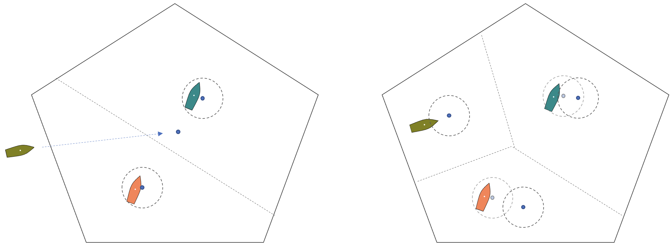
Figure 1.2: Evolving Set Point: (Left) As the a vehicle transits to the muster region, its set point is the center of the region. Other vehicles may already reside in the muster region. Their set points are the center of their Voronoi cells. (Right) As the vehicle enters the region, the Voronoi partition changes for both the entering vehicle and the vehicles previously in the region. The set point for each vehicle is the center of its cell. Vehicles that were previously at their set point may need to move to reaquire their set point, depending on the capture and activate thresholds given in the behavior configuration parameters.


Note that the arrival of the new vessel in the region will immediately alter the overall partition and shape of cells for the vehicles that were already in the region. And as the new vessel traverses to its initial set point, the partition will evolve and its own and other set points will also move.

A vehicle that had previously achieved its set point and ceased motion, may begin to move again if its set point has moved sufficiently far away from its present position. As mentioned in the previous section, motion will not resume from a captured state, until the distance between the vehicle and the set point becomes larger than the activate radius.
The Muster behavior may be preferred when the mission requires some number of vehicles to proceed to a region to gather and wait (muster), until some next phase of the mission is to begin. Although each vehicle is typically also running a collision avoidance behavior, a goal of the muster behavior is to move the vehicles in a manner that achieves a degree of vehicle separation perhaps obviating the need for the collision avoidance behavior. A further goal of the muster behavior is that no prior location assignments are required, and the behavior works with any number of other vehicles needing only periodic position information from its neighbors.

2 The OnRunState() Loop
The onRunState() function is executed by the behavior on each iteration of the helm when the behavior is not idle. In this section the key steps of this function are reviewed. Details of certain steps will be discussed in separate sections.

As the step 1, the behavior obtains the current positions of ownship and all contacts also in the muster region. This set of positions is denoted by V:


The vehicle position and the muster region, given as a configuration parameter, are sufficient for creating the Voronoi partition discussed in step 2. The Voronoi partition, P, is comprised of the union of non-overlapping Voronoi cells, for ownship and n contacts in the muster region:


Given the full partition, P, in step 3 the set point xsp, ysp is obtained from the Voronoi cell for ownship, Pos, as described in Section 3.3. Given the set point, the muster mode is determined in step 4, based own ownship position relative to the setpoint, and the most recent mode setting, described in Section 6.1.

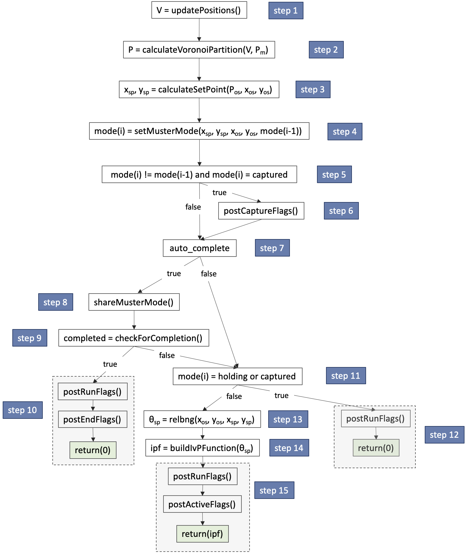
Figure 2.1: Muster Behavior Loop Flow Chart: Each iteration of the Muster behavior will proceed through the steps shown, with branching determined by sensed events and the behavior configuration. Details of each step are discuss in their own sections as indicated.


In step 5, if the muster mode is determined to be newly set to "captured", the behavior will publish any capture flags configured for this mission, as described in Section 4.2.

In step 7, the behavior configuration parameter, auto_complete, is examined. This parameter is described in Section 5.4, and is used in situations when ownship may take a configured action when or if all collaborating vehicles have obtained the captured state in the muster region. If auto_complete is true, in step 8, the behavior will share its current mode with all other collaborating vehicles. This message and the means for sharing are described in Section 5.2. In step 9, the behavior will examine the current modes of all other vehicles. If ownship and all vehicles are in the "captured" state, then the ownship Muster behavior will complete. The completed behavior will post its end flags in step 10, and the behavior will not produce an objective function, instead returning null.

If the behavior does not have auto_complete enabled, or if not all members in the group are in the "capture" mode, in step 11 the ownship muster mode is examined. If the mode is holding or capture, the Muster behavior will not produce an objective function, returning null. If the mode is either transiting or activated, an objective function will need to be produced. In step 12, the set point heading angle, θsp, is calculated as the relative bearing from the current ownship position to the set point. In step 13, an objective function will be created and returned, using the set point heading angle, as described in Section 6.3.

The OnRunState() Behavior Loop Pseudocode [top]
The onRunState() flowchart in Figure 2.1 is represented in pseudocode in the algorithm below.


3 Generating the Voronoi Partition and Set Point
The Muster behavior uses the Voronoi partion of a muster region based on ownship position and the positions of other collaborating vehicles in the muster region. Motion of the vehicle is based on a policy of movement relative to the partition. The Voronoi partition is described below in Section 3.2. The motion policy is described in Section 6, and the set point policy is described in Section 3.3.

3.1 Obtaining Vehicle Positions [top]
In step one of the behavior run-loop the position of ownship and all collaborating vehicles is obtained. Ownship position is found in the current navigation solution in the variables NAV_X and NAV_Y. Positions for other vehicles are found in the variable NODE_REPORT which contains the contact name and position among other fields. On each iteration, the behavior processes all new updates for these three variables.

The Muster behavior maintains a data structure, VoronoiField, which holds (a) the muster region polygon and (b) a mapping from vehicle name to a position in the X-Y plane. The position of ownship is always updated. If a contact is determined to be within the muster polygon, it is updated. Otherwise it is removed from the VoronoiField data structure.
Limitation: stale contacts, group names


3.2 Voronoi Partitions [top]
In step 2 of the behavior run-loop the Muster behavior uses the notion of a Voronoi Partition, as shown in Figure 3.1. While a Voronoi partition can be applied in unbounded space in any dimension, in our case the partition will always be defined in the local X-Y plane, and always be bounded by a given convex polygon region.

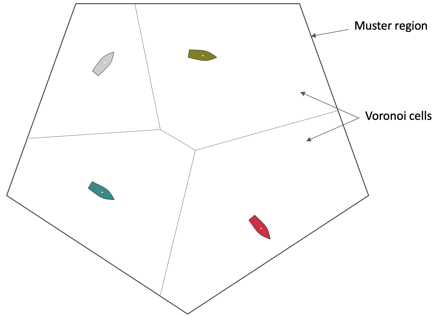
Figure 3.1: Voronoi Partition: Vehicle positions in the muster region form a Voronoi partition over the region. As the vehicles move, or exit and enter the region, the partition evolves correspondingly.


In this step the behavior uses the VornoiField data structure created in step 1 and populated with ownship and contact positions. The Voronoi partition algorithm is a member function defined on this structure and will produce a partition on demand. For each cell of the partition, an inner wall is determined by a line in space where all points on the line are equi-distant between the two vehicles on either side of the line. The muster region polygon will be be denoted at P. The convex polygon comprising the local cell for vehicle i will be denoted as  . The Voronoi cell for ownship is denoted as Pos. The area of a local cell will be denoted as

A few additional points: (a) The area of each cell may be far from equal across cells, (b) A local cell can be calculated for ownship with local information of neighboring vessels only, (c) The vehicle locations determine the partition. However, the Voronoi partition can used to guide vehicle motion by setting a policy of where a vehicle should move with respect to its own current cell and position within the cell. This is discussed next.


3.3 The Set Point and Muster Mode [top]
In step 3 of the run-loop, the Muster behavior calculates a set point, (xsp, ysp). This is a point in the X-Y plane toward which the behavior will prefer to move. By default the set point is the center of the orthogonal convex hull of its Voronoi cell as shown in Figure 3.2. When the vehicle is completely outside the muster region, the set point is the center of the muster region.

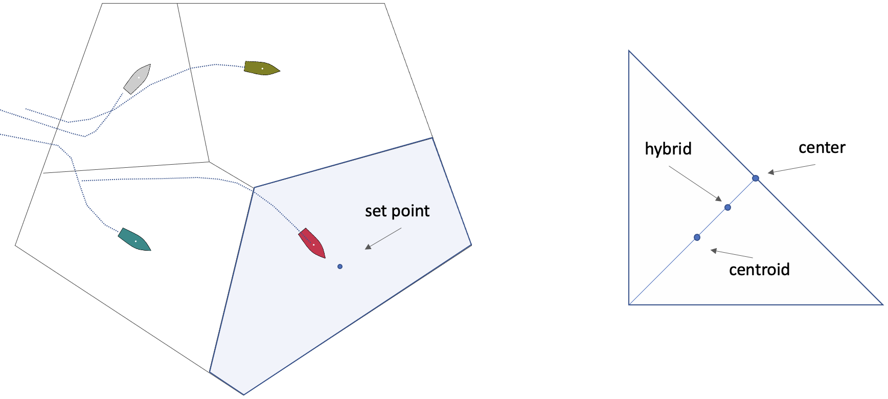
Figure 3.2: Muster Set Point: The set point for a vehicle is typically the center of the Voronoi cell for the vehicle, as shown on the left, where the center is the median x-y value of the orthogonal convex hull. The set point policy could also be the centroid of the cell, or a hybrid of the two policies as shown on the right.


Alternative set point methods include centroid and hybrid. In the hybrid mode, the set point is the mid point between the center and centroid points. This parameter is set with configuration parameter:

setpt_method = center

Other experimental set point methods are discussed in Section ???.


4 Muster Modes and Capture Flags
The muster mode is a key distinction that determines the operation of the behavior on each iteration of the run-loop. It determines the output of the behavior in terms of the objective function, and the output in terms of posted flags.

4.1 Muster Modes and Configured Criteria [top]
In step 4 of the behavior run-loop, the behavior determines its current muster mode. The current muster mode depends on three state variables, (a) ownship postion, (xos,  , (b) the set point, (xsp, ysp), and (c) the muster mode from the previous iteration. It also depends on three configuration parameters, the muster_region, the capture_radius, and the activate_radius.

The Muster behavior will have one of five modes. When the behavior is idle, the mode is simply off. When it is not idle, and is outside the muster region, the mode is transiting. Once inside the muster region, before it has reached the capture radius, the mode is activated. When it reaches the set point capture radius, the mode changes to captured. If the vehicle then slips beyond the capture radius, but is still within the active radius, the mode is holding. In the captured and holding modes, the Muster behavior will not produce an objective function, as discussed in Section ???. This is shown in Figure 4.1.

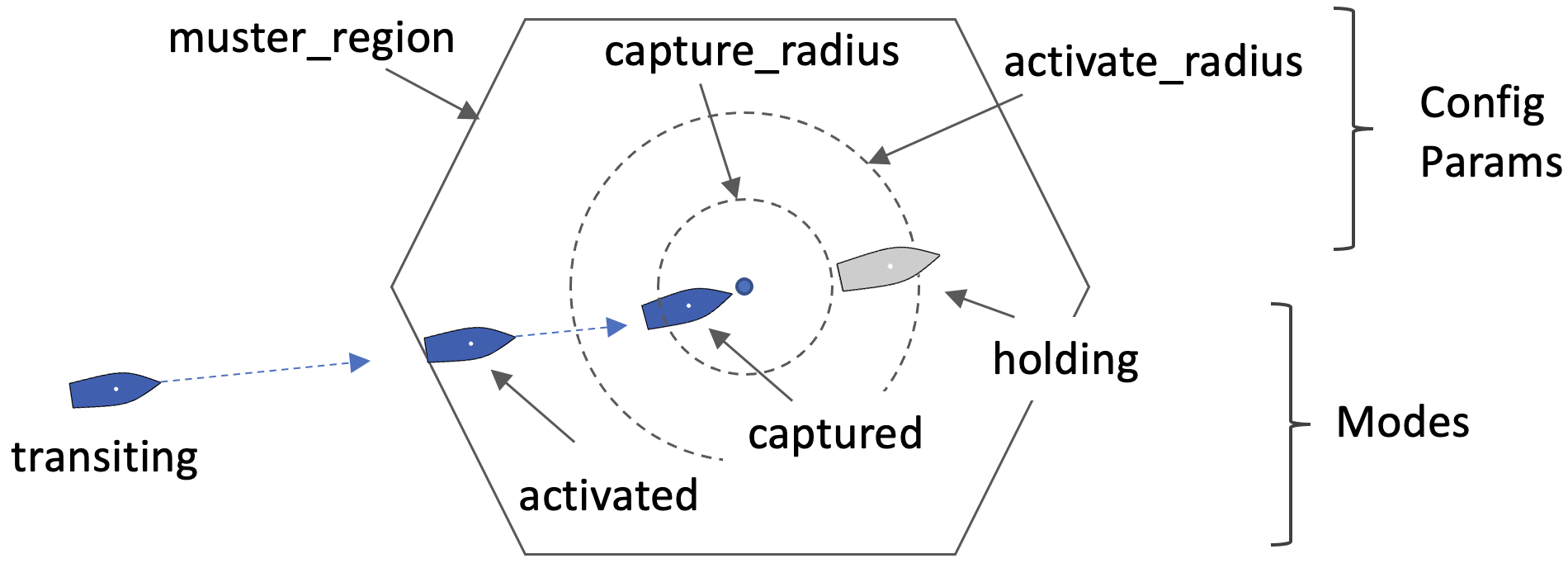
Figure 4.1: Muster parameters and modes: The vehicle is transiting to a given muster region. Once inside the region we say the behavior is activated as drives toward the center of the region. When it is within the capture radius, the mode becomes captured. When or if the vehicle opens range beyond the capture radius, but still within the activate radius, we say the vehicle is the the holding state.


The use of the activate radius is to allow the vehicle to proceed nearly all the way to the set point. As discussed in Section ???, the behavior will cease to produce an objective function once it has reached its capture radius. Unless there are other behaviors running, this normally means that the vehicle stops in the water. However, the Voronoi partition, and thus the set point can be quite fluid if the neighboring vehicles are moving. To limit trivial starting and stopping, the activate radius is an additional threshold, to avoid resuming motion when the vehicle distance to the set point becomes higher than the capture radius.


4.2 Muster Capture Flags [top]
Each time the Muster behavior transitions into the captured mode, a set of capture flags may be posted. These flags are similar to general behavior flags such as end flags. They are set with the configuration parameter:

capture_flag = variable=value

where the variable is any MOOS variable and the value is any string or numerical value. Any number of capture flags, including zero, may be configured.

The behavior supports a few macros specific to the Muster behavior, that may be useful in conjuction with the capture flag. The REGION macro will expand to the name of the muster region. The ODO_ACTIVE macro will expand to the total odometry distance while this behavior has been in the activated state.


5 Auto Completion
The motivation for creating the Muster behavior was to coordinate mustering with other vehicles, and keep them safely separated in the region. The behavior as described so far is capable of doing this so long as it knows the positions of the other vehicles. Sometimes we will say that ownship has arrived when it enters the region and reaches its set point. Sometimes it is useful to know that all other vehicles have also arrived, perhaps transitioning into some other activity when they have all arrived. This is the purpose of the optional auto completion feature.

5.1 Enabling Auto Completion [top]
Step 7 of the run-loop checks to see if auto completion has been enabled. This is a configuration parameter of the behavior:

auto_complete = true

The default value is false.


5.2 Sharing the Muster Mode to Other Vehicles [top]
When auto completion is enabled, in step 8 of the run-loop, the behavior will package up a status message to be shared with all other vehicles.

MUSTER_COLLAB = "vname=deb, region=alpha, state=holding"

The first component is ownship name. The second is the name of the muster region. As discussed in Section 9, the behavior may be configured with multiple possible muster regions, so this component is included. The third component is the muster mode.

When the behavior publishes this variable, it uses a built-in behavior function to wrap this message in an outgoing inter-vehicle message. The convention in MOOS-IvP is to wrap it in a posting to NODE_MESSAGE_LOCAL to be shared with all other variables. So the actual posting will look more like:


 NODE_MESSAGE_LOCAL = "src_node=deb,src_app=pHelmIvP,src_bhv=muster,
                      dest_node=all,var_name=MUSTER_COLLAB,
                      string_val="vname=deb,region=one,state=holding"


To accomplish this in the behavior code, this is a single line:

postXMessage("MUSTER_COLLAB", "vname=deb, region=alpha, state=holding"


This built-in convenience function is defined for all behaviors and will package the outgoing message in the NODE_MESSAGE_LOCAL variable.


5.3 Checking for Completion [top]
In step 9, with auto completion enabled, the behavior will assess the muster mode of itself and all other vehicles sharing their muster mode. The behavior maintains a mapping from vehicle name to mode, along the lines of:

- ben: holding
- cal: captured
- deb: tranisting


In step 9, all incoming MUSTER_COLLAB messages are parsed and the mapping is updated. If all vehicles are in either in the completed or holding mode, then the collaborative group mustering is regarded as completed. The consequences of completion are the normal consequences for a completed IvP Helm behavior. End flags will be posted and the behavior will be removed from the helm, freeing any trace of the behavior from the helm memory space.

Current limitations: The criteria for group completion is that the muster mode for ownship, and all other vehicles sharing their muster modes, are checked. This list is of other vehicles is fluid and built from received messages. A new entry in the map is added when a new vehicle has sent a report. If there is a member of the group that is outside of communications range, its muster mode will be unknown to the group. For example if the goal is to send five vehicles to a muster region and one vehicle is very far behind, the first four vehicles might draw the conclusion that collaborative mustering is complete when all four arrive. Other options for defining group completion are being considered including explicitly naming the group, or defining a numerical groups size requirement.

Further note: It is possible that a collaborating vehicle ceases to communicate at some point, either due to a comms range issue, or vehicle failure. If the last muster mode of this vehicle was not holding or completed, it could prevent the group from ever reaching a consensus of group completion. To guard against this, the muster behavior will check for staleness of muster mode updates. An entry in the mapping will be dropped after 30 seconds if a new muster mode update is not received. Currently this time value is hard-coded.


5.4 Muster Completion [top]
In step 10, following a positive determination of completion, the behavior will post endflags. Endflag support is implemented generally for all behaviors. The only unique components of this for the Muster behavior are the macros supported for solely for the Muster behavior described in Section ???.

Note also that completion, by default, will result in the deletion of the behavior from the helm and its memory. Like all behaviors, destruction of the behavior upon completion may be overridden with the perpetual=true behavior. This allows the Muster behavior to be configured with multiple muster regions, transiting to one after another without destruction of the behavior. Configuration of the Muster behavior for multiple regions is discussed in Section ???.


6 Implemention of the Motion Policy
If the Muster behavior does not auto-complete (steps 7-10), then the behavior motion policy is invoked (steps 11-13). These steps may produce an IvP objective function that will participate in the helm's multi-objective optimization stage of decision making. These steps are described next.

6.1 Application of the Muster Mode [top]
In step 11, the muster mode is examined. If the mode is either completed or holding, then the Muster behavior is essentially content with its current position relative to the set point. It will not produce an objective function.

In step 12, the Muster behavior will post runflags and return null. In this case the Muster behavior is said to be in the running mode, distinct from the active mode. Recall, for IvP behaviors generally, the active mode is a special case of the running mode where an objective function is actually produced. So runflags, if they are configured for this behavior, will be posted. Again, the only unique components of this for the Muster behavior are the macros supported for solely for the Muster behavior described in Section 8.


6.2 Determining the Orientation to the Set Point [top]
In reaching step 13, the determination has been made that this behavior will produce an objective function. The objective function will drive the vehicle toward the set point. The relative bearing from ownship's current position to the set point needs to be determined. This value is denoted θsp. For example:

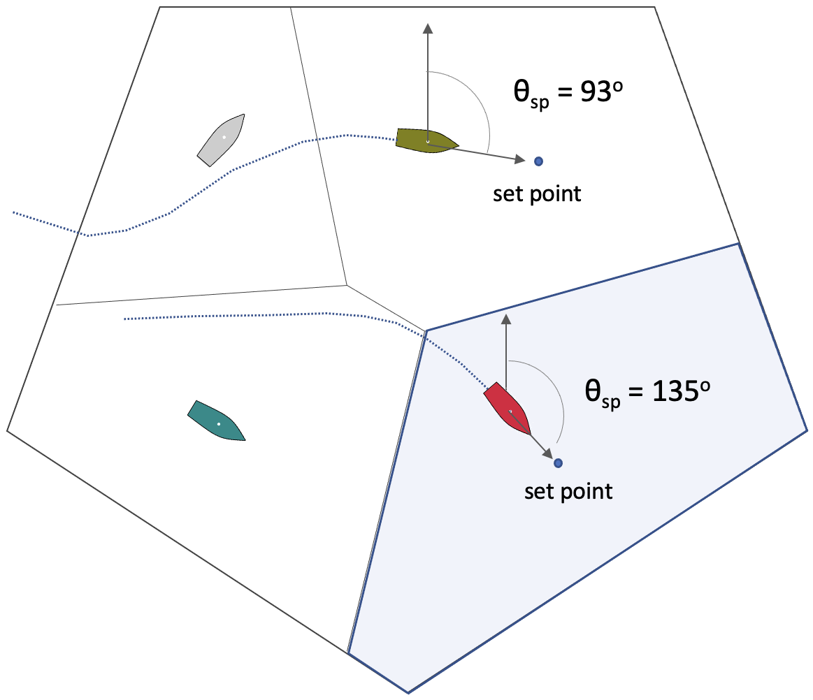
Figure 6.1: Determination of Ownship Orientation Toward the Set Point: The value θsp denotes the relative bearing from ownship to the set point. The set point position was determined previously in setp 3.


Once θsp has been set, the IvP objective function may be constructed in the next step.


6.3 Construction of the IvP Objective Function [top]
In step 14, the IvP objective function will be created. The behavior will use tools from the IvPBuild toolbox, the ZAIC_PEAK, ZAIC_SPD and OF_Coupler tools to create the objective function shown on the right in Figure 6.2. The ZAIC tools are used for making the two single-variable utility functions shown on the left, which are then coupled using the OF_Coupler tool into the single heading-speed IvP function.


Figure 6.2: The IvP Objective Function for the Muster Behavior: The IvP function for the Muster behavior is composed from the two single variable utility functions, defined over speed and heading. These two utility functions are coupled into a single heading-speed utility function shown on the right.


The speed utility function ingests the speed behavior configuration parameter, determining the peak value of the function. The off-peak values lower than the set speed degrade in utility slower than the off-peak values higher than the set speed. This generally results in a more "patient" performance when the behavior is competing with other behaviors like collision avoidance. The inferred patience is due to the propensity of a compromise to simply reduce speed rather than change heading to resolve a potential collision.

The final step of creating the IvP function is to first normalize the function to ensure the overall function has a minimum utility of 0, and maximum utility of 100. The behavior priority weight, set with the general behavior parameter priority, will then be applied to the IvP function. This behavior has a static priority weight policy, unchanging regardless of circumstances. Once it is set in the mission file, it will remain the same throughout the mission unless it is adjusted using the general updates mechanism by some entity external to the Muster behavior.


6.4 Active Participation of the Muster Behavior [top]
In step 15, the Muster behavior will actively participate in the Helm decision stage by producing IvP function. When a running behavior does indeed produce an objective function, this behavior is said to be in the active state. Both the run flags and active flags will be posted if the user has configured any. Again, the only unique components of these flag postings for the Muster behavior are the macros supported for solely for the Muster behavior described in Section 8.


Performance Metrics [top]
There are a handful of metrics that will be used in evaluating a Voronoi partition, and the process of forming the partition:

- separation: The minimum distance between any two vehicles
- balance: The standard deviation on measured area for all cells
- efficiency: The time or distance travelled before all vehicles require no further motion to achieve balance or separation objectives
- stability: The number of instances where a vessel needs to resume motion to re-achieve objectives.

For the Muster behavior, separation is the primary motivation. While separation usually comes with balance, it is not necessarily so. Separation will be measured not only as an end-state value when all vehicles have essentially "arrived". Separation in terms of closest point of approach (CPA), during all phases will be measured, and evaluated for instances of breach of collision threshold.


7 Performance Metrics and Macros
A number of performance metrics are implemented for the Muster behavior. The value of a metric will be held locally in the behavior and exposed through one of the supported macros. For example, the area of the vehicle's local Voronoi cell is measured and available for posting in any flag with the macro $(CELL_AREA). If the user is interested in tracking this information, the mission could be configured to post this using the runflag parameter''

runflag = MEASURED_AREA = $(CELL_AREA)


Or if this information is only needed once, when all collaborating vehicles have arrived and the behavior is about to complete (step 10), then an end flag could be used:

endflag = FINAL_MEASURED_AREA = $(CELL_AREA)


while metrics are exposed as macros, the complete list of macros supported for the Muster behavior includes certain information that is not considered a metric, such as the name of the muster region. This section will first describe the supported metrics and corresponding macros, followed by any remaining macros.

7.1 Performance Metrics Related to the Voronoi Field [top]


7.2 Performance Metrics Related to Odometry [top]


7.3 Non Metrics Related Macros [top]


7.4 Summary of all Macros [top]
Voronoi Field ========================= Aspect ratio for cell i Average aspect ratio Largest aspect ratio Area of region Area of cell i Perimiter of cell i Area Standard deviation
Min distance ownship to any other vehicle Min distance between any two vehicles
Local ========================== Odometry total Odometry since running Odometry inside region Odometry total Odometry total


8 Supported Macros for the Muster Behavior
muster mode setpoint policy

9 Configuring the Muster Behavior with Multiple Muster Regions

9.1 Configuration Parameters [top]
Certain configuration parameters available to Muster behavior are are unique to the Muster behavior and others are inherited one or more base classes. Here all parameters are presented, with details on those unique to the Muster behavior.

Parameters for the Muster Behavior [top]

Listing 9.1 - Configuration Parameters for the Muster Behavior.

| Parameter | Description |
| activate_radius: | The radius from the set point, beyond which the behavior will resume the production of a non-zero speed objective function to close range to the current set point. The default is 12 meters. Section 6.1. |
| auto_complete: | Enable configured action to take place when or if all collaborating vehicles achieve their captured state. The default is "off". Section 5.4. |
| capture_flag: | A set of flags to be posted each time the behavior transitions to the captured mode. Section 4.2. |
| capture_radius: | The range to the set point, within which the behavior will enter the captured mode. Section 3.3. |
| holding_policy: | The holding policy determines what objective function, if any, is produced when the behavior is in the captured or holding mode. Section 6.3. |
| muster_region: | A string representing a convex polygon, or a string matching the label of a previously loaded muster region. Section 1. |
| post_prox_poly: | If true, post a VIEW_POLYGON message to representing the belief of the local Voronoi cell. The default is false. Section ???. |
| region_in_flag: | A flag published when the behavior is active and the vehicle enters the muster region. Section ???. |
| region_out_flag: | A flag published when the behavior is active and the vehicle exits the muster reegion. Section ???. |
| setpt_method: | One of several options for the algorithm determining the set point. The default is center. Other options are centroid, or hybrid. Section 3.3. |
| setpt_viewable: | If true, a VIEW_POINT method will be published for rendering the set point as it evolves. The default is true. Section 3.3. |
| speed: | The transit speed to the set point, in meters per second. The default is zero. |
| stale_nav_thresh: | The number of seconds between ownship navigation updates before a stale warning is produced. The default is 5 seconds. Section ???. |
| visual_hints: | Visual hints related to the rendering of the set point size, set point color, and set point label color. The defaults are 4, yellow, and off, respectively. |


Listing 9.2 - Example Configuration Block.

 Behavior = BHV_MusterX
 {
   // General Behavior Parameters
   name       = muster_
   pwt        = 100
   condition  = MODE = MUSTERING
   updates    = MUSTER_UPDATES

   active_flag = AVOID=true

     capture_radius = 10
    activate_radius = 25
      auto_complete = true
       capture_flag = AVOID=false

   stale_nav_thresh = 10
       setpt_method = center
     setpt_viewable = false
     post_prox_poly = false

     region_in_flag = MUSTER=true
    region_out_flag = MUSTER=false

     holding_policy = curr_hdg

       visual_hints = setpt_size = 5
       visual_hints = setpt_color = blue
       visual_hints = setpt_label_color = off
 }


Document Maintained by: mikerb@mit.edu
Page built from LaTeX source using texwiki, developed at MIT. Errata to issues@moos-ivp.org.
 Get PDF
