Maintained by: mikerb@mit.edu  Get PDF
1 The Convoy Behavior
1.1 Generation and Removal of Markers
1.2 Capturing a Marker
1.3 The Ideal Convoying Steady State
1.4 Speed of the Convoying Vehicle - The Speed Policy
1.4.1 Speed Policy Configuration Parameters
1.4.2 Speed Policy Compression
1.4.3 Off-Peak Speed Preferences
1.5 Visual Preferences
1.6 Output of the Convoy Behavior in the Form of Publications
1.6.1 Baked In Publications of the Convoy Behavior
1.6.2 Event Flag Publications of the Convoy Behavior
1.6.3 Event Flag Macros of the Convoy Behavior
1.7 Performance Metrics
1.8 Configuration Parameters
1.9 Terms and Definitions
1.10 Known Shortcomings - Work in Progress
1 The Convoy Behavior
This behavior will drive the vehicle to follow another specified vehicle by following virtual markers dropped by the lead vehicle. The vehicle following the lead vehicle is referred to as the convoying vehicle. As the lead vehicle transits, the convoying vehicle will make note of the lead vehicle's position and periodically note as markers, the position of the lead vehicle. The convoying vehicle will continuously transit to the rear-most marker. Upon reaching the rear-most marker it will proceed to the next rear-most marker, and so on.

This behavior can be compared to the Trail behavior. The goal of the Trail behavior is to continually aim toward a point at a relative angle and distance from the lead vehicle. When the Trail behavior is using a trail angle of 180 degrees, it may look similar to a Convoy behavior when both vehicles are on a long linear transit. However, as shown in Figure 1.1, when the lead vehicle turns, the Convoy behavior will continue to follow the trajectory of the lead vehicle, while the Trail behavior will deviate to steer directly toward the point currently 180 degrees behind the lead vehicle.


Figure 1.1: Convoy vs. Trail When traveling on a linear path, the Convoy behavior is similar to the Trail behavior with the trail angle set to 180 degrees, as shown on the left. But as the lead vehicle maneuvers, the Convoy behavior will follow the path of the lead vehicle, whereas the Trail behavior will continuously aim for the point currently 180 degrees behind the lead vehicle, as shown on the right.


The Convoy behavior may be preferred when it is important to have the following vehicle traverse the same path of the lead vehicle, regardless of their relative angle at any one given instant. For example, if the lead vehicle is driven by a human, or is autonomous but has a more capable sensor system, it may serve as a guide through obstacles, bridge pylons, or other hazards.

1.1 Generation and Removal of Markers [top]
A marker is comprised of the observed X-Y or Lat/Lon position of the lead vehicle at some previous point in time. The lead vehicle typically does not communicate marker information explicitly to the convoying vehicle. Rather the convoying vehicle notes and stores this information from incoming node reports of the lead vehicle. Incoming node reports may be derived via AIS, direct communications, or through sensors on the convoying vehicle. The source of the lead vehicle position information is irrelevant to this behavior.


Figure 1.2: Convoy Markers: The convoying vehicle heads toward the rear-most marker behind the lead vehicle. As the convoying vehicle reaches each marker, the reached marker is dropped, and then proceeds to next rear-most marker as shown on the left. In a lagging situation, shown on the right, the convoying vehicle is still heading toward the rear-most marker, but the convoying vehicle's path, while it is lagging, may not closely follow the lead vehicle's path.


The marker tail is the set of all markers. The marker tail length is the sum of line segments between markers plus the range from the lead vehicle to the lead marker, which is the most recently added marker just aft of the lead vehicle. The aft marker is the oldest marker in the marker tail and presumably the marker that the convoy behavior is driving toward. The range between markers is set with the configuration parameter inter_mark_range. The default value is 10 meters.

A new lead marker is added as the lead vehicle moves, whenever the range between the lead vehicle and the current lead marker becomes greater than the inter_mark_range. A marker is removed from the rear of the tail if the tail length becomes longer than tail_length_max. The default of this parameter is 150 meters. By this policy, the tail length should always be less than or equal to tail_length_max. The rear-most marker may also be removed when or if the convoying vehicle captures the marker. Capturing is discussed next.


1.2 Capturing a Marker [top]
As the convoying vehicle approaches its next marker, there are conditions continually examined to determine when it has reached, or captured, the marker. The simplest criteria is when the vehicle has reduced its range to the marker to be less than the capture_radius, a configuration parameter with default value of 5 meters. This is shown on the left in Figure 1.3. Occasionally the convoying vehicle may miss the marker, perhaps due to external environmental forces, or other mission considerations that pull the vehicle off a direct path to the marker. If the capture_radius were the only criteria for capturing a marker, the convoying vehicle may be forced to loop back to try again. If the capture_radius is too large, then the vehicle would be free, perhaps too early, to begin heading toward the next marker. If the lead vehicle is on a highly nonlinear path, a very large capture_radius may result in the convoying vehicle deviating too much from the lead vehicle's path.


Figure 1.3: Capturing a Marker: The \bvarr{capture_radius} determines when a convoying vehicle reaches a marker (left). If the convoying vehicle gets within the \bvarr{slip_radius} range of the marker, the marker will be considered reached when or if the range to the marker begins to increase (right).


The slip_radius configuration parameter specifies a larger range to the marker than the capture_radius. Once the convoy vehicle enters within range of the slip_radius, the marker will be considered captured if the angle between ownship, the marker and next marker, is less than 90 degrees.
The default value for the slip_radius is 20 meters. The slip_radius range, as a rule of thumb, should be 2-4 times bigger than the capture_radius. A configuration warning will be generated if the slip_radius is less than the capture_radius.

When a marker is captured, the Convoying behavior removes the marker from its internal marker tail. Markers are removed from the tail when either they are captured by the convoying vehicle, or when the marker tail length exceeds the maximal length set by the max_tail_length parameter.


1.3 The Ideal Convoying Steady State [top]
The ideal, or steady-state, situation for the convoying vehicle is to be positioned, on the marker tail, at the proper convoy range to the lead vehicle, and matching the speed of the lead vehicle. The convoy range is the length of the marker tail plus the distance between the rear-most marker and position of the convoying vehicle, as shown in Figure 1.4.

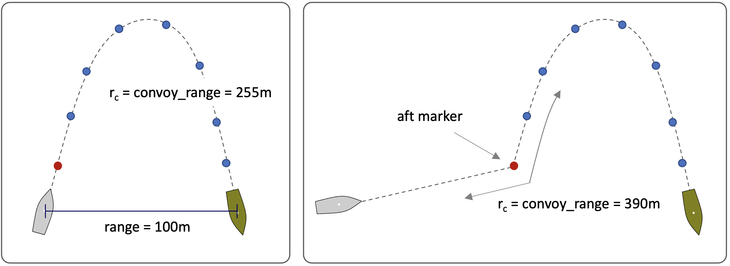
Figure 1.4: Convoy Range: The convoy range is the length of the marker tail plus the range from the rear-most marker to the current position of the convoying vehicle. This will be greater than or equal to the linear range between the two vehicles.


The ideal convoy range is synonymous with the value given by the parameter tail_length_max. The convoy range delta is the difference between the current convoy range and the ideal convoy range. The speed of the convoying vehicle in the ideal convoying steady state, is simply the current speed of the lead vehicle. The convoy speed delta is the difference between the current speed of the convoy vehicle and the lead vehicle.

It is also sometimes useful to have a notion of when the vehicle is in the ideal convoying steady state. As a general approximation we will say it is in the ideal state if:

- the convoy range delta is less than the inter mark range plus the slip radius, and
- the convoy speed delta is less than a quarter of the current lead vehicle speed, and less than a quarter of the convoy vehicle speed.


1.4 Speed of the Convoying Vehicle - The Speed Policy [top]
The convoy behavior uses a speed policy to determine which speed best keeps the vehicle at the ideal convoy range to the lead vehicle. The policy is based on (a) the current convoy range, (b) the speed of the lead vehicle, and (c) the direct range between vehicles. The latter is only used as a measure for triggering a safety full-stop. Depending on the current convoy range delta, the speed policy will identify a set speed. The set speed will either match, overshoot, or undershoot the lead vehicle speed depending on whether the current convoy range is ideal, too far, or too close respectively.

When the current convoy range is not ideal, the degree of the overshoot or undershoot in the set speed is linearly proportional to the difference between the convoy range and ideal convoy range. There are several configuration parameters that determine the speed policy. These parameters are conveyed in Figure 1.5. Note that for the ideal convoy range there is a tolerance. Within this tolerance range, the set speed will simply be the lead vehicle speed, even if the current convoy range is not quite equal to the ideal convoy range.

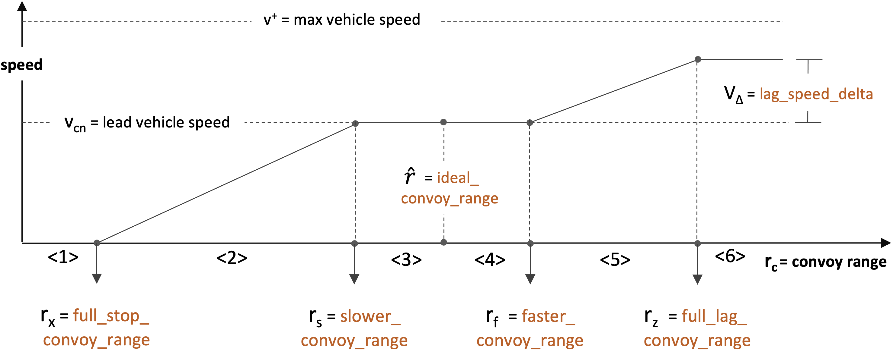
Figure 1.5: The Convoy Speed Policy: The preferred speed of the convoy behavior is determined by the speed policy, which depends on (a) the speed of the lead vehicle, (b) the current convoy range, and (c) the current direct range between vehicles. The speed policy is configured by the user and may be dynamically adjusted during a mission. There are six correction modes identified, based on the relationship between the current convoy range and the ideal convoy range.


The Correction Mode: [top]
The relationship between the current convoy range and the ideal convoy range determines which of six correction modes apply at the moment. They are shown in Figure 1.5, and named:

- full stop: The current convoy range is less than or equal to the full_stop_convoy_range.
- close: The current convoy range is greater than the full_stop_convoy_range, but less than or equal to the slower_convoy_range.
- ideal close: The current convoy range is greater than the slower_convoy_range, but less than or equal to the ideal_convoy_range.
- ideal far: The current convoy range is greater than the ideal_convoy_range, but less than or equal to the faster_convoy_range.
- far: The current convoy range is greater than the faster_convoy_range, but less than or equal to the full_lag_convoy_range.
- full lag: The current convoy range is greater than the full_lag_convoy_range


1.4.1 Speed Policy Configuration Parameters [top]
The speed policy is set directly with the following five parameters as an example. Note the value of the ideal convoy range does not directly influence the speed policy. Speed adjustments faster or slower are only made when the current convoy range is outside the steady speed span. The ideal_convoy_range parameter is used in setting the correction mode, and to have a metric to measure mission performance against. If left unspecified, it will be automatically set to the mid point between the faster_convoy_range and the slower_convoy_range

full_stop_convoy_range=20 \\ slower_convoy_range=40 \\ ideal_convoy_range=50 \\ faster_convoy_range=60 \\ full_lag_convoy_range=80

From Figure 1.5, the legal relative values are conveyed. For example, the slower_convoy_range cannot be less than the full_stop_convoy_range. The relative magnitude for each adjacent pair of parameters is checked both on helm startup, and after any dynamic update to the behavior during a mission. If a violation is detected upon startup, the helm will start in the malconfig state and will be unable to deploy until the behavior file is fixed and the helm re-launched. If the violation is detected at runtime, the behavior update will simply be rejected and a run warning will be posted.


1.4.2 Speed Policy Compression [top]
The speed policy, comprised of the configuration parameters described above, may be dynamically adjusted mid-mission to compress or expand the convoy range between vehicles. This could be done using the updates variable, by providing new values for the speed policy parameters. For example, if the updates variable were CONVOY_UPDATES, then the following posting would adjust the speed policy:

CONVOY_UPDATES = full_lag_convoy_range=50 # faster_convoy_range=40 # slower_convoy_range=30

While the above is supported, a perhaps easier method is to specify a single compression value. This parameter ranges between 0 (no compression), and 1 (full compression). Since a fully compressed policy would essentially amount to a policy comprised of either full catch up speed or full stop, compression is capped at 0.9. For example, given the example speed policy above in Section 1.4.2, the full CONVOY_UPDATES line above could be accomplished with the simpler line:

CONVOY_UPDATES = compression=0.5

Compression is applied to all speed policy intervals except the safety-critical full_stop_convoy_range. The idea is conveyed in Figure 1.6 below.

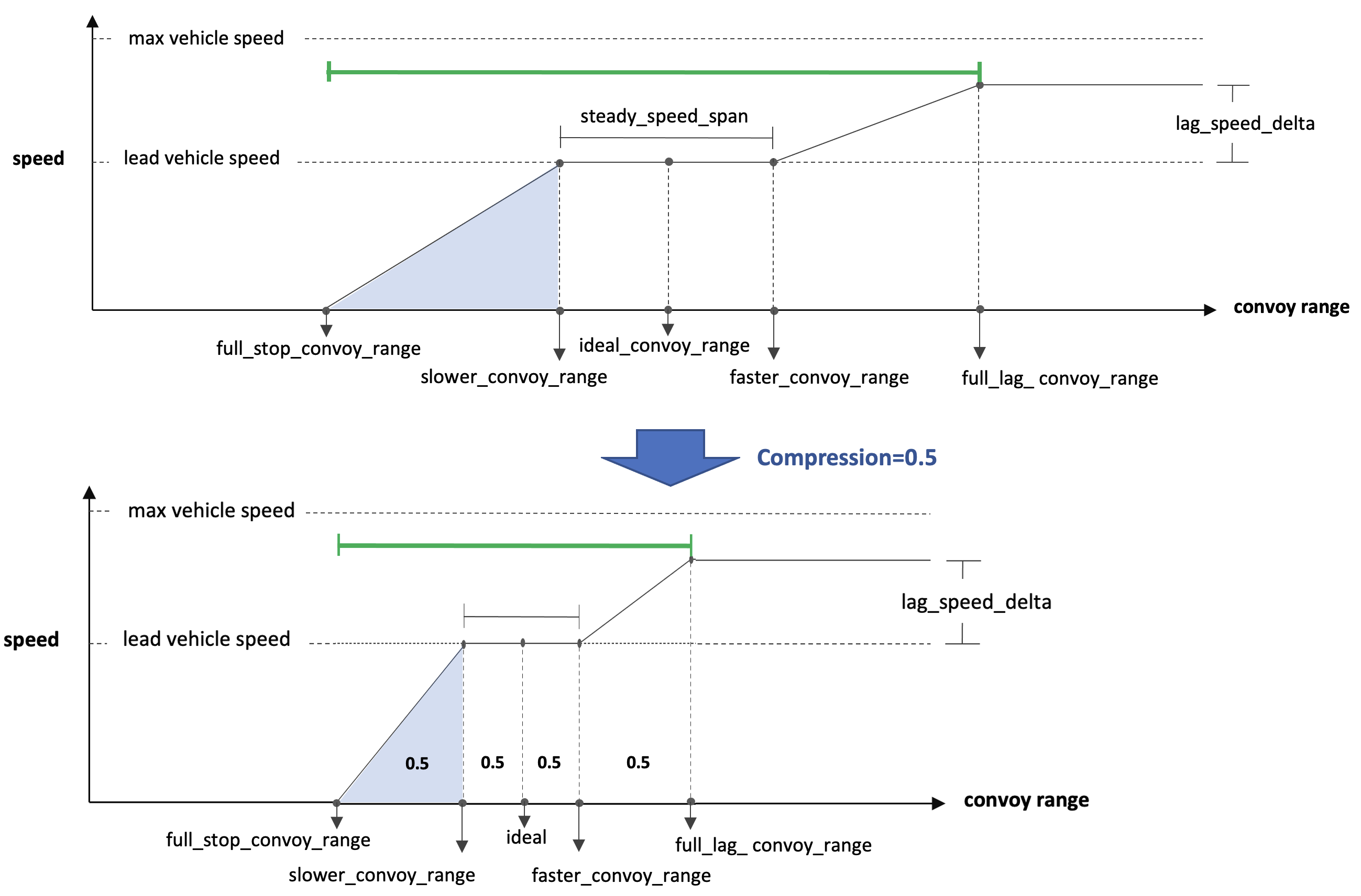
Figure 1.6: Speed Policy Compression: A single compression value in the range of [0,0.9] may be applied to a compression policy. All intervals will be compressed by this value, except the safety-critical \bvvar{full_stop_convoy_range}.


Note that by setting compression=N either on startup, or through the updates variable, the compression is applied to the original uncompressed policy. In other words, two successive updates with a compression value of 0.5, will result in a policy compressed at 0.5, not 0.25.


1.4.3 Off-Peak Speed Preferences [top]
The convoy behavior, like all behaviors of the IvP helm, will produce an objective function. The objective function of the convoy behavior is defined over possible course (desired heading) and speed choices. The convoy behavior constructs this 2D objective function by combining an objective function (utility function) defined over speed and one defined over heading. In this section the speed utility function is discussed.

The helm is configured with a decision space over all decision variables. This decision space is propagated to all behaviors of the helm, including the convoy behavior. The decision space for the speed component will contain both a min speed value (typically zero) and a max speed value. The max speed may be the max speed of the vessel, or the highest allowed operational speed, or may be set for some other reason. In any event, the speed utility function maps speed to utility, from the min speed to the max speed. As shown in Figure 1.7, the peak of this function is the set speed, produced from the speed policy. The set speed and speed utility function are dynamic, recalculated at each iteration of the helm based on situational input.

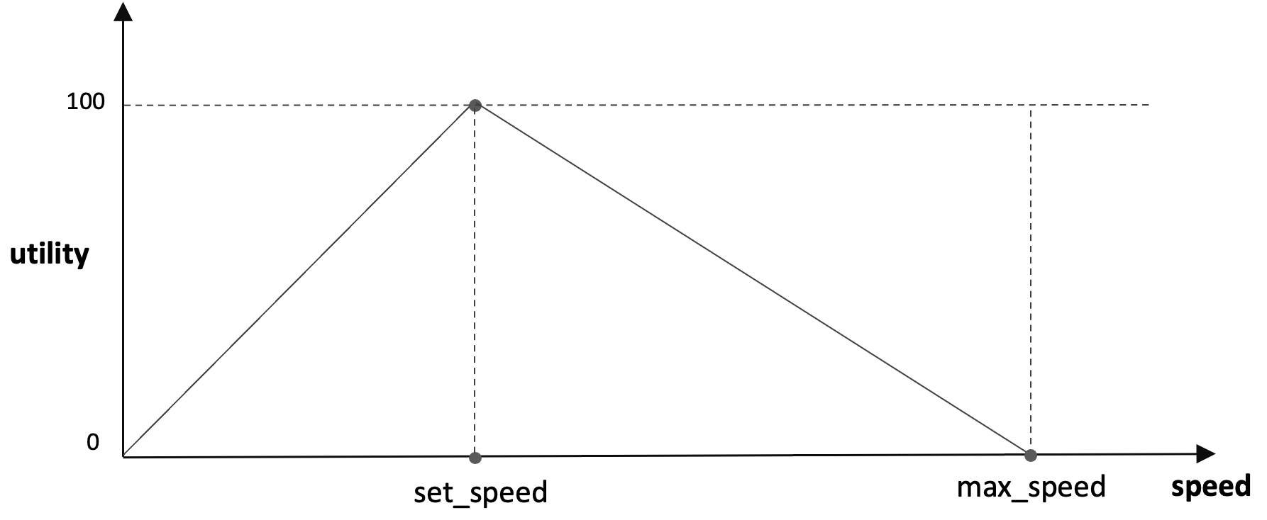
Figure 1.7: Speed Utility Function: Given a set speed, the speed utility function is marked by the optimal utility at the set speed with linearly decreasing utility for speed differing from the set speed.


Note in Figure 1.7, by default, the utility at both zero speed and the maximum speed are set to zero. However, the convoy behavior will vary either the zero speed or max speed utility to a non-zero value depending on the correction mode, described in Section 1.4. For example,

Figure 1.8 shows the speed utility function when the correction mode is far. Since the current convoy range is larger than the ideal convoy range, the correction mode is far, and the set speed already is somewhat higher than the lead vehicle speed, to close the convoy range. However, in this correction mode, off-peak utility of speeds higher than the set speed are skewed higher by setting the utility of the max speed to 50 percent of the max utility. In this way, if the convoy behavior needs to coordinate and compromise with another behavior, it is more likely to strike a compromise with a speed higher than the set speed.

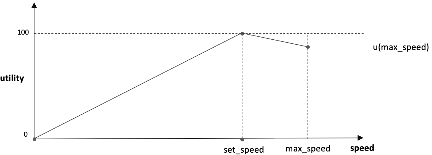
Figure 1.8: Speed Utility Function When Lagging: In a lagging situation, the set speed is chosen accordingly to close range on the lead vehicle. Additionally, the utility of higher speeds degrade linearly at a slower rate than the utility of speeds lower than the set speed. If the behavior is in a compromise situation with another behavior and the optimal set speed is precluded by the other behavior, compromise speeds are more likely to be higher than the set speed.


Likewise, if the convoy vehicle has a correction mode of close, Figure 1.9 shows the speed utility function. Since the current convoy range is smaller than the ideal convoy range, and the correction mode is close, the set speed already is somewhat lower than the lead vehicle speed, to open the convoy range. However, in this correction mode, off-peak utility of speeds lower than the set speed are skewed lower by setting the utility of the zero speed to 50 percent of the max utility. In this way, if the convoy behavior needs to coordinate and compromise with another behavior, it is more likely to strike a compromise with a speed lower than the set speed.

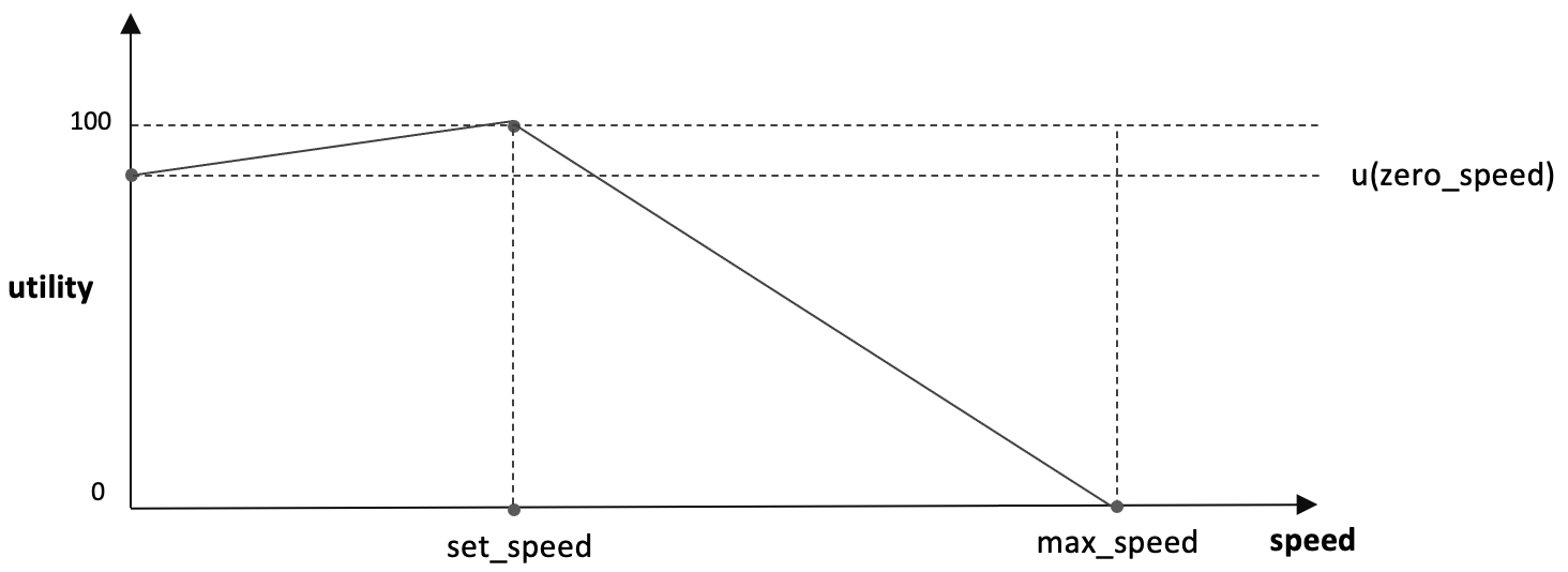
Figure 1.9: Speed Utility Function When Close-In: In a close-in or tailgating situation, the set speed is chosen accordingly to open range to the lead vehicle. Additionally, the utility of slower speeds degrade linearly at a slower rate than the utility of speeds higher than the set speed. If the behavior is in a compromise situation with another behavior and the optimal convoy set speed is precluded by the other behavior, compromise speeds are more likely to be slower than the set speed.


The speed utility function is skewed in this manner, based on the correction mode as described in the two examples above. For the other correction modes, the following policy is used:


| Correction Mode | Zero-Speed Utility | Max-Speed Utility |
| close | 50 | 0 |
| ideal_close | 25 | 0 |
| ideal_far | 0 | 25 |
| far | 0 | 50 |
| full lag | 0 | 75 |


1.5 Visual Preferences [top]
The primary visual artifact produced by the convoy behavior is a posting to MOOS variable VIEW_POINT, for representing the markers in the marker tail. This variable is recognized by the pMarineViewer GUI application. An example posting is:

VIEW_POINT = x=-5.1,y=-50.31,label=ben_deb_14,vertex_color=red,vertex_size=6

The label is formed from the convoy vehicle name plus the lead vehicle name plus an index. As markers are captured and deleted by the behavior they are "erased" by re-posting with the same label, setting the field active=false.

VIEW_POINT = x=-5.1,y=-50.31,active=false,label=ben_deb_14

An example of the artifacts rendered in pMarineViewer in a typical mission is shown in Figure 1.10.

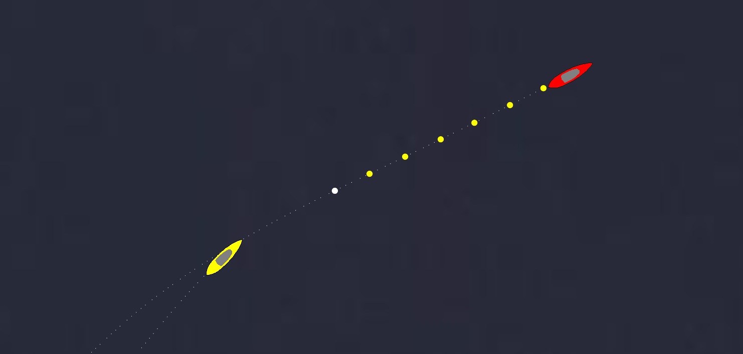
Figure 1.10: Convoy Behavior Visual Artifacts: The Convoy behavior will post points of a chosen size and color to represent the working marker tail. The aft marker is typically rendered in white. In this case the marker colors are set to automatically match the vehicle color for extra clarity.


The marker size and color, and the marker label color, may be set with configuration parameters:

visual_hint = marker_color = green
visual_hint = marker_label_color = white
visual_hint = marker_size = 6

The default marker color is blue. The default marker label color is off. The default marker point size is 4.


1.6 Output of the Convoy Behavior in the Form of Publications [top]
All behaviors produce two kinds of output, (a) an objective function, and (b) one or more publications to MOOS variables. The former was discussed in Section ???, the latter is discussed here. MOOS variable publications take two forms, (a) publications that are baked into the code that are not user configurable, and (b) user configurable publication based on event flags. The tendency in newer behaviors is to use fewer baked in publications and instead support a rich set of event flags that are further configurable with event macros. The specifics of publications for the Convoy behavior are discussed here.

1.6.1 Baked In Publications of the Convoy Behavior [top]
Baked in publications are part of a behavior's implementation and the format of these publications are not configurable by the user. The Convoy behavior has three core publications:

- VIEW_POINT: Intended to be consumed by pMarineViewer during a mission, or alogview during mission playback. This variable was discussed in detail in Section 1.5.
- CONVOY_SPD_POLICY: A description of the prevailing speed policy.
- CONVOY_STAT_RECAP: A recap of convoy configuration state that typically does not change between iterations. See the example below.
- CONVOY_RECAP: A recap of convoy state that changes often and includes the core performance metrics and other state variables. See the example below.


An example of the static recap publication:

CONVOY_STAT_RECAP = follower=abe,leader=deb,ideal_rng=25,compression=0,index=0


An example of the speed policy publication:

 CONVOY_SPD_POLICY = full_stop_rng=2,vname=eve,slower_rng=23,ideal_rng=25, [=\=]
                     faster_rng=27,full_lag_rng=40,lag_spd_delta=2,        [=\=]
                     max_compress=0.9

An example of the dynamic recap publication:

 CONVOY_RECAP = convoy_rng=17.4,vname=gus,rng_delta=-7.5,tail_cnt=6,    [=\=]
                cmode=close,tail_rng=4.5,tail_ang=3.44,mark_bng=46.41,  [=\=]
                almnt=49.84,set_spd=0.661,cnv_avg2=0.905,cnv_avg5=0.867,\
                mx=30.6,my=-11.8,mid=0

The mx, my, and mid components are the aft marker X, Y location and marker ID respectively. The cmode compoent it the most recently observed correction mode.

Although the format of these variables cannot be changed in the mission file, they can be remapped to a different variable name, or they may be suppressed if desired, using the IvP Behavior post_mapping parameter:

post_mapping = CONVOY_RECAP,silent
post_mapping = CONVOY_RECAP,MY_PREFERRED_RECAP_VAR

By default, the CONVOY_RECAP will be posted whenever the behavior drops the aft marker, typically by reaching it. If the user prefers a more frequent posting, on every iteration of the behavior, the following parameter is used:

post_recap_verbose=true

The default setting for this parameter is false.

If the preference is to publish a smaller subset of the recap, or a simple numerical posting more readily consumable for plotting, use the event macros instead. For example, if one only wants the alignement value (the almt field in the recap), an event flag can be used:

convoy_flag = CONVOY_ALIGNMENT=$[ALIGNMENT]

which is published on every iteration of the convoy behavior when active. Or for less frequent publications, whenever a marker is reached:

marker_flag = CONVOY_ALIGNMENT=$[ALIGNMENT]

See Section 1.6.3 for further event flag and macro options.


1.6.2 Event Flag Publications of the Convoy Behavior [top]


1.6.3 Event Flag Macros of the Convoy Behavior [top]

Listing 1.1 - Macros supported by the Convoy Behavior.

| Macro | Description |
| \cvar{AVG_SPD2}: | The average speed of the lead vehicle over the last previous two seconds. |
| \cvar{AVG_SPD5}: | The average speed of the lead vehicle over the last previous five seconds. |
| \cvar{COMP}: | The current compresssion setting. See Section 1.4.3. |
| \cvar{CONVOY_RNG}: | The current convoy range. See Section 1.3 for the definition of the convoy range. |
| \cvar{IDEAL_RNG}: | The current ideal convoy range. See Section 1.3 for the definition of the ideal convoy range. |
| \cvar{LEADER}: | The name of the leader vehicle, in lower case. |
| \cvar{CMODE}: | The correction mode for the most recent set speed calculations. See Section 1.4. for the definition of the correction mode. |
| \cvar{SET_SPD}: | The current set speed. See Section 1.4 for the definition of the set speed. |
| \cvar{RECAP}: | A summary of the Convoy behavior settings and state. |
| \cvar{TAIL_CNT}: | The number of markers currently in the marker tail. See Section 1.1 for the definition of the marker tail. |
| \cvar{TRK_ERR}: | The current range to the marker tail augmented with recent history of retired markers. Meant to measure the deviation from the path of the lead vehicle. See Figure 1.12 for the definition of the track error. |

An example of the \cvar{RECAP} macro expansion is:

$(\cvar{RECAP}) = \var{leader=ben, follower=abe, convoy_range=32.1, ideal_range=30, compression=0.25}


1.7 Performance Metrics [top]
Performance metrics are values derived from the current ownship and contact positions and headings, plus the current marker tail and the parameter set by the user for the ideal contact range.

- tail range: The range between ownship and the aft marker.
- tail angle: The angle between the three points given by ownship position, the aft marker and the near-aft marker. By definition this value cannot be more than 180. This number is reported at 180-x so that minimal, near zero is optimal. See Figure 1.11.
- marker bearing: The absolute relative bearing of the aft marker to ownship. This number is in the range of [0, 180]. See Figure 1.11.


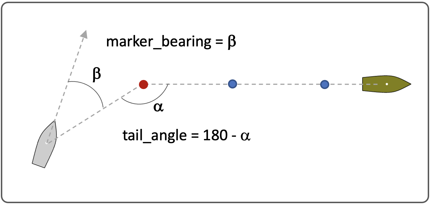
Figure 1.11: Tail Angle and Marker Bearing: The tail angle is angle at the aft marker between ownship and the near-aft marker. The marker bearing is the absolute relative bearing of the aft marker to ownship.


- alignment: Alignment is the sum of tail angle and marker_bearing.
- convoy range delta: The difference between the current convoy range and the ideal convoy range.
- track error: The distance to the marker tail with the marker tail augmented by a few recently retired markers. This is meant to convey how well ownship is following the lead vehicle. See Figure 1.12.


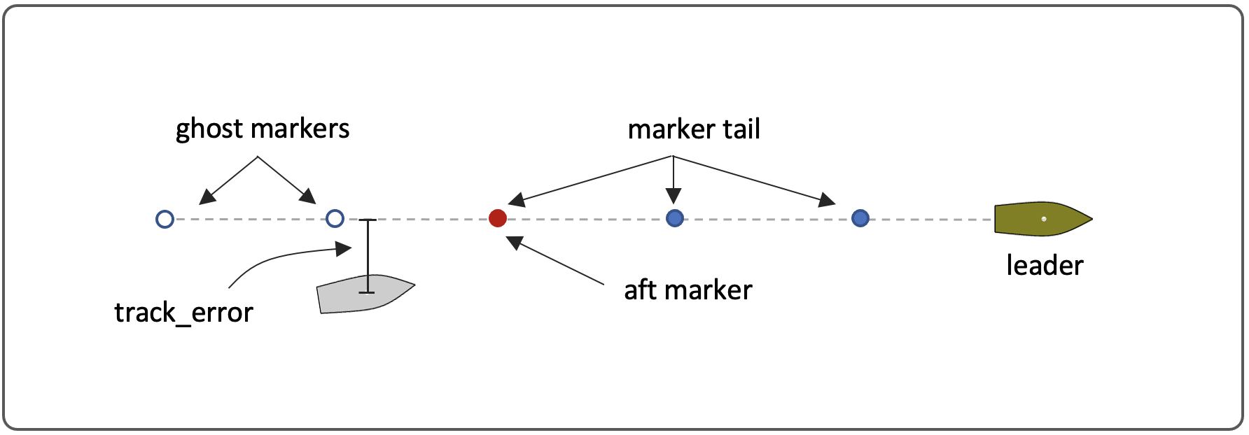
Figure 1.12: Track Error: The track error is the distance between ownship and the track line segments, formed by the marker tail and few recently retired markers, ghost markers.


The metrics are published in the CONVOY_RECAP posting as discussed in Section 1.6.1. They may also be published via event flags and macros as discussed in Section 1.6.3.


1.8 Configuration Parameters [top]
Certain configuration parameters available to Convoy behavior are are unique to the Convoy behavior and others are inherited one or more base classes. Here all parameters are presented, with details on those unique to the Convoy behavior.

Parameters for the Convoy Behavior [top]

Listing 1.2 - Configuration Parameters for the Convoy Behavior.

| Parameter | Description |
| capture_radius: | The range between the convoying vehicle and the next marker before the marker can be considered captured. Section 1.2. |
| compression: | The degree to which the ideal convoy range and the entire speed policy is compressed to achieve closer convoy ranges. This parameter ranges between [0, 0.9]. Section 1.4.3. |
| faster_convoy_range: | The convoy range above which the behavior will produce preferred speeds that are faster than the lead vehicle speed. Section 1.4. |
| full_stop_convoy_range: | Range between ownship and the lead vehicle, within which the preferred ownship speed is zero. Section 1.4. |
| full_lag_convoy_range: | The convoy range above which ownship will apply maximum speed in order to close the convoy range. Maximum speed is given by the lead vehicle speed plus the lag_speed_delta. Section 1.4. |
| inter_mark_range: | The range between neighboring markers. Section 1.1. |
| ideal_convoy_range: | The ideal or target convoy range to be achieved by the behavior. Section 1.4. |
| radius: | Same as capture_radius. |
| lag_speed_delta: | The difference between preferred ownship speed and the lead vehicle speed when the convoy range is at or higher than the full_lag_convoy_range. Section 1.4. |
| slip_radius: | The range between the convoying vehicle and the next marker, within which the marker will be considered captured when or if the vehicle begins to open range to the marker. Section 1.2. |
| slower_convoy_range: | The convoy range within which the behavior will produce preferred speeds that are slower than the lead vehicle speed. Section 1.4. |
| tail_length_max: | The maximum marker tail length, beyond which the behavior will drop the oldest marker. Section 1.1. |
| visual_hints: | One or more hints governing the preferred size and color of markers. Section 1.5. |


Listing 1.3 - Example Configuration Block.

 Behavior = BHV_ConvoyV21
 {
   // General Behavior Parameters
   name       = convoy_
   pwt        = 100
   condition  = MODE = convoying
   updates    = CONVOY_UPDATES
   templating = spawn

   // Contact Behavior Parameters
   contact    = unset_ok

   // Convoy Behavior Parameters
             radius = 3.0
        slip_radius = 15.0
   inter_mark_range = 3
    tail_length_max = 40

   full_stop_convoy_range = 2
      slower_convoy_range = 23
       ideal_convoy_range = 25
      faster_convoy_range = 27
    full_lag_convoy_range = 40
          lag_speed_delta = 2.0

    marker_flag = CONVOY_RECAP=$[RECAP]
    marker_flag = CONVOY_RANGE=$[CONVOY_RNG]
   visual_hints = marker_color=$(COLOR)
   visual_hints = marker_color_label=off
   visual_hints = marker_size=12
 }


1.9 Terms and Definitions [top]

- aft marker: The oldest marker, typically farthest to the lead vehicle of all the markers, and typically the marker currently being driven toward by the Convoy behavior. Section 1.1.
- captured marker: The marker reached by the following vehicle. Section 1.1.
- convoy range: The actual current distance along the marker tail from the lead vehicle to the following vehicle. Section 1.3.
- compression: Modification of the speed policy to adjust all convoy range parameters, except the full stop convoy range, to be smaller than the original speed policy values. Section 1.4.
- convoy range delta: The absolute difference between the ideal convoy range and the desired convoy range. Section 1.3.
- convoy speed delta: The absolute difference between the lead vehicle speed and the following vehicle speed. Section 1.3.
- ideal convoy range: The desired convoy range. Section 1.3.
- lagging: A following vehicle is lagging the lead vehicle when the convoy range is beyond the ideal convoy range, namely beyond the range set in the faster_convoy_range. Section 1.4.
- lead marker: The most recently created marker, typically closest to the lead vehicle of all the markers. Section 1.1.
- marker: A point in the X-Y plane representing a prior location of the lead vehicle, to be driven toward by the convoying or following vehicle. Section 1.1.
- marker tail: The set of markers used for determining the following vehicle's path to match the lead vehicle. Section 1.1.
- marker tail length: The distance between the lead vehicle and the the newest marker plus the total length of segments between markers. Section 1.1.
- range: The direct range between the lead and following vehicle.
- set speed: The speed chosen to modify or hold the convoy actual convoy range compared to the ideal convoy range. It is the output of the speed policy. Section 1.4.
- speed policy: The policy governing the selection of the set speed given the current convoy range, lead vehicle speed, and absolute direct range between vehicles. Section 1.4.
- track error: The distance between ownship and the marker tail, where the marker tail is augmented by a few recently retired ghost markers. See Figure 1.12.


1.10 Known Shortcomings - Work in Progress [top]

- Automatic compression. Speed policy compresses as the lead vehicle slows, and decompresses as the lead vehicle speeds up.
- Name of the leader is a macro option
- Follow auto-informs heartbeat style to the leader


Document Maintained by: mikerb@mit.edu
Page built from LaTeX source using texwiki, developed at MIT. Errata to issues@moos-ivp.org.
 Get PDF
