Vehicles

Software Trees
Equipment
- Servicing the Heron
- Configure New Heron
- GPS Config Solution
- Heron Batteries
- PABLO
- GPS/E-Stop Equip
- Known Issues
- Imu Calibration Tips
- Repair and parts
Network
Attic
Help Topic: Heron M300 Introduction
Maintained by: mikerb@mit.edu  Get PDF
Introduction to the Heron M300 Vehicle
The current fleet stored at the Pavilion includes six robotic vehicles, Clearpath Heron M300 vessels, named Evan, Felix, Gus, Hal, Ida and Jing.
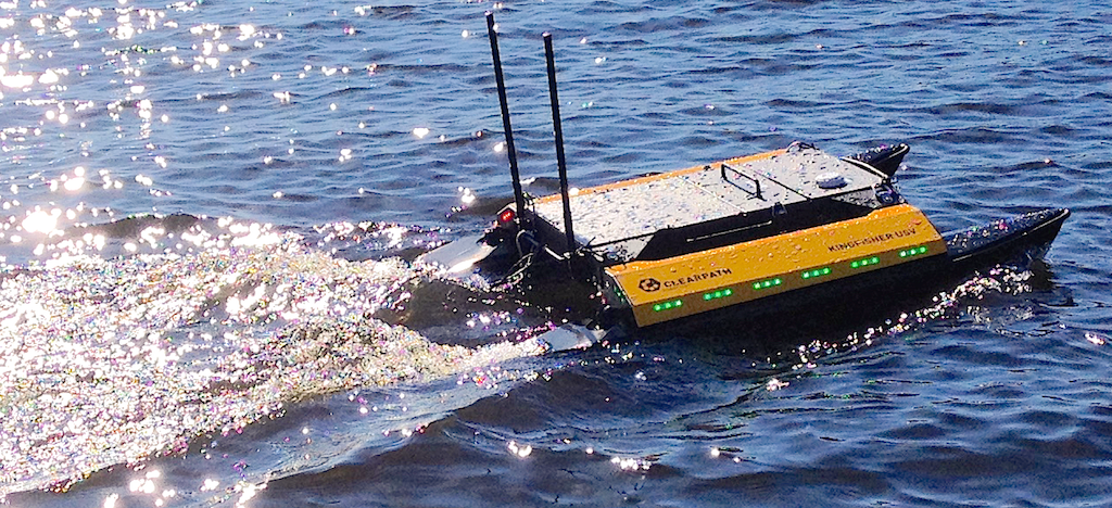
Figure 1.1: The Clearpath Robotics Heron M300 on the river.
The Clearpath Heron M300 is a collapsible catamaran-style vessel that can be deployed by a single person, although it is easier to handle with two people. Jet-drive motors are installed at the stern of each pontoon that allow efficient forward thrust and poor reverse capability. The main body of the vehicle has three sections:

| Section | Description |
| Computing | The forward section contains the front seat embedded computer with a 2.2GHz Intel ATOM processor and support equipment for motor control, communications, and sensing. |
| Battery | A single battery package is installed above the main electronics bay in the front section. It is used to power propulsion and for computing. |
| Payload | The large aftward tray is the payload bay where the back seat computer (the PABLO unit) is housed. This section has removable top and bottom covers. The bay includes three waterproof ports: two USB-A connectors and an Ethernet receptacle. |
Table 1.1: Sections of the M300 vessel
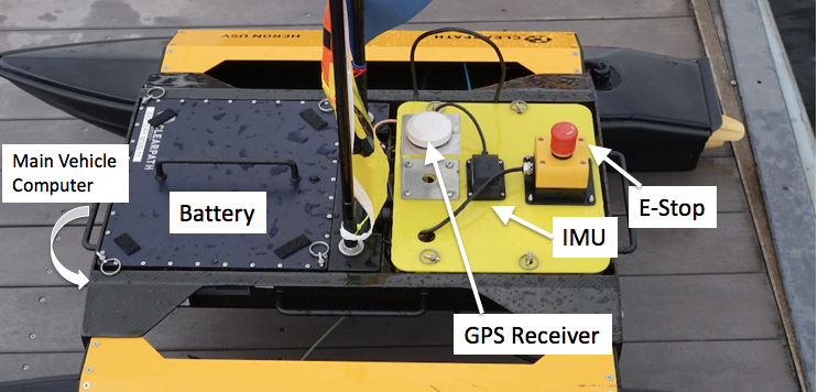
Figure 1.2: Some main components of the M300 USV with payload, sensor modifications for the MIT variant. The E-Stop equipment is unique to the MIT variant. The GPS and IMU sensors ship with the vehicle, but their locations and mounting have been modified in the MIT variant for better performance and access.
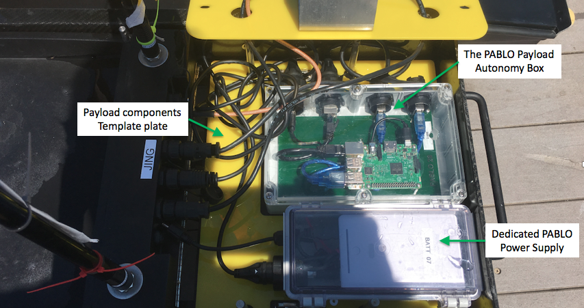
Figure 1.3: In the MIT variant, the payload compartment contains both the payload autonomy box (PABLO) and a dedicated power supply for the PABLO (the smaller box in the photo). Both components sit in a custom template cut with holes to fit the PABLO and battery box. The latter helps to ensure a position for smooth cable arrangments.
Navigation Sensors [top]
The GPS antenna is a white puck mounted on the lid of the payload bay cover as in Figure 1.2. An inertial motion unit with integrated digital compass is also mounted on the payload cover lid. Both sensors connect to and are processed by software on the frontseat computer. Output from these sensors is published by the frontseat, as defined by the Clearpath Wire Protocol, shared to the PABLO computer running the payload autonomy (MOOS-IvP) software.
Vehicle Batteries and Charging [top]
The lab has a number of battery packs available for use. Several of the batteries are suitable for on-dock preparations but do not include enough capacity for sustained deployment. Batteries are stored and charged on the metal rack at the rear of the lab. One battery package is charged by two charger units. To charge a battery, set it on the side so that the connector is on the top. Plug in the charger with the red plugs matching. If necessary, orient the chargers so that the LED indicators are facing outward. Red or amber light indicates charging; completed charging shows a green light.
Charging Batteries [top]
Each charger has a switch to select 1A or 2A charging. The 2A rate is quicker but may contribute a shorter battery life. Therefore, use 2A when the battery will be needed again on the same day and 1A otherwise. {\it Be sure to set the switch on both chargers to the same setting.} If all chargers are in use and not displaying a green light, leave the battery needing charge on the bottom shelf.
Installing Batteries [top]
Always pull the M300 out of the water and well onto the dock to change the battery. {\sc Do not change the battery while the vessel is in the water}. Change the batteries in a place where there is no chance of dropping the battery into the river.
The M300 has a latch on each side that retains the battery. To remove a battery, undo the latches and pull upward on the handle. If it is stuck, give a light yank or seek assistance from the lab instructor. To install a battery, first verify that the battery terminals align with the power port on the vehicle. Insert the battery straight down and push it in until it is almost flush with the vehicle. After the battery is firmly in place, install all four pins on each of the four posts. Do not power on the vehicle unless the battery is secured.
Storing and Moving [top]
The M300 units are usually stored on carts or on a shelf inside the lab, although it is acceptable to leave units on the floor at the rear of the lab. With only one handler it is advisable to remove the battery before lifting or moving the vehicle. With two people the battery's additional weight is typically manageable. The vehicle carts are provided for moving the M300s around the dock and lab space. Take care to secure the cart once if used on the docks, to make sure they don't roll away. They will sink if rolled into the river.
Deploying and Retrieving [top]
Always have the correct remote control handy when the M300 is in the water near the dock. To deploy, take the vehicle off the cart and set it on the dock with the thrusters pointing into the river. Verify that the remote can control the thrusters. Gently push the vehicle into the water and use the remote to transit away from the dock. It is inadvisable to leave the vehicle drifting near or tied to the dock. Wake from passing motorboats can pummel the vehicle into the floating platform.
To retrieve an M300 vessel, use the remote control to bring it back to the dock head first. Lift and pull it onto the dock by the front handle. Using the side handles, one or two people can lift it onto the cart.
Manual Remote Control [top]
Remote control (RC) operation is suitable for transiting from or returning to the dock or as an emergency override. The flat slider switch adjacent to the LCD display turns the unit on and off. When the RC is powered on, the switch on the upper-left (SW2) of the face selects when the vehicle's computer (switch down) or the remote (switch up) has control. When enabled, the RC will override the on-board computer. RC range is approximately 100 feet. When not in use, the remote control should be turned off and connected to charge on its hook at the rear of the lab.
Page built from LaTeX source using texwiki, developed at MIT. Errata to issues@moos-ivp.org. Get PDF