
- Design Overview
- MOOS Overview
- Example Mission Alpha
- IvPHelm as a MOOS App
- Helm Autonomy
- Behavior Properties
- BHV_Waypoint
- BHV_OpRegion
- BHV_OpRegionV24
- BHV_Loiter
- BHV_PeriodicSpeed
- BHV_PeriodicSurface
- BHV_ConstantDepth
- BHV_ConstHeading
- BHV_ConstantSpeed
- BHV_MaxDepth
- BHV_GoToDepth
- BHV_MemoryTurnLimit
- BHV_StationKeep
- BHV_FixedTurn
- BHV_LegRun
- BHV_ZigZag
- BHV_Timer
- BHV_TestFailure
The LegRun Behavior
Maintained by: mikerb@mit.edu  Get PDF
src: project-pavlab/bhvdocs/bhv_legrun
1 The LegRun Behavior
2 Intended Mission Use
2.1 The Core Algorithm
2.2 The OnRunState() Loop
2.3 Construction of the IvP Objective Function
2.4 Active Participation of the LegRun Behavior
2.5 Configuration Parameters
2.6 Publications
3 The Waypoint Engine
3.1 Flags and Macros
3.2 Flags and Macros
1 The LegRun Behavior
The LegRun behavior enables a vehicle to repeatedly traverse back and forth over a legrun trackline prescribed by two vertices. After reaching the end of the trackline, the vehicle switches into a Williamson turn mode to ensure the vehicle aligns with the trackline when starting in the other direction. The idea is shown in Figure 1.1.
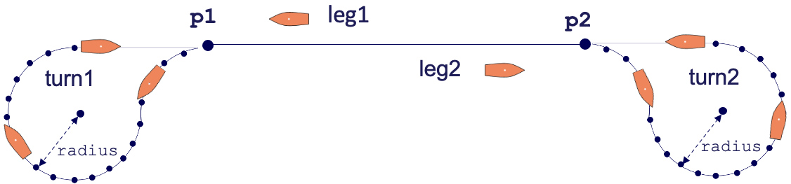
Figure 1.1: The LegRun Behavior: A vehicle traverses back and forth along a trackline given by two vertices. At each end the vehicle performs a Williamson Turn to be aligned with the trackline at the very beginning of the trackline.
The behavior may be configured with a single vehicle speed, or a schedule of speeds, changing on each legrun. As with any other helm behavior, configuration parameters may be changed dynamically through its updates variable. As such, this behavior support several configuration parameters for changing the length and orientation of the legrun trackline while the behavior is running. Dynamic in-mission modifications to the turn characteristics are also supported. The support for in-mission adjustments is to allow an operator to gauge a mission for safety or other metrics during a mission and adjust as needed without needing to halt and restart the vehicle mission, thereby saving valuable test range time.
2 Intended Mission Use
The LegRun behavior generally is used for structuring a set of vehicle performance tests. If the performance tests involved first putting the vehicle on a straight course, then performing and measuring a maneuver, the LegRun behavior can be used to repeatedly set up the vehicle on the straight line. The basic trajectory created by the behavior without any test, is shown in Figure 2.1:
Figure 2.1: LegRun Behavior: The vehicle traverses a trackline given by two points, and conducts a Williamson turn at the end of each trackline to ensure it is aligned with the trackline when it resumes in the other direction.
The behavior can be configured to post a user-specified flag at some user-specified mid-point of each leg. This flag can be used to (a) switch the LegRun behavior into idle mode and (b) cue another behavior to begin. Presumably the other behavior will utilize an end flag that will result in the resumption of the LegRun behavior. In Figure 2.2, a FixedTurn behavior is triggered in the middle of a leg, completes its turn, and resumes the original leg.
Figure 2.2: LegRun Behavior with Turn Test: During the trackline portion of the LegRun behavior, the behavior posts a flag to trigger a FixedTurn behavior to conduct a full turn, measuring the turn radius, and then resumes the trackline portion of the LegRun behavior.
Other types of "shake-out" behavior used with a LegRun behavior include the FullStop behavior, and the ZigZag behavior.
2.1 The Core Algorithm [top]
The LegRun behavior is comprised of (a) a leg between two vertices, (b) two Williamson turns at either end of the leg. The vehicle initially will traverse to a point on the leg, and then proceed indefinitely through each turn, ideally beginning each leg closely aligned with the leg angle at the start of the turn. When or if the behavior is interupted and enters the idle state, the resumption of the behavior will return to whichever leg it was on when it entered the idle state. If the behavior becomes idle when turning, it will re-enter the init state when it resumes running.
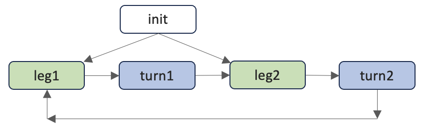
Figure 2.3: LegRun Modes: The behavior will initially begin in the init mode to find an initial leg, and then will transition between the modes as indicated as it proceeds through each stage.
2.2 The OnRunState() Loop [top]
The onRunState() function is executed by the behavior on each iteration of the helm when the behavior is not idle. In this section the key steps of this function are reviewed. Details of certain steps will be discussed in separate sections.
As the step 1, the behavior obtains the current position of ownship denoted by:
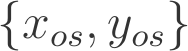
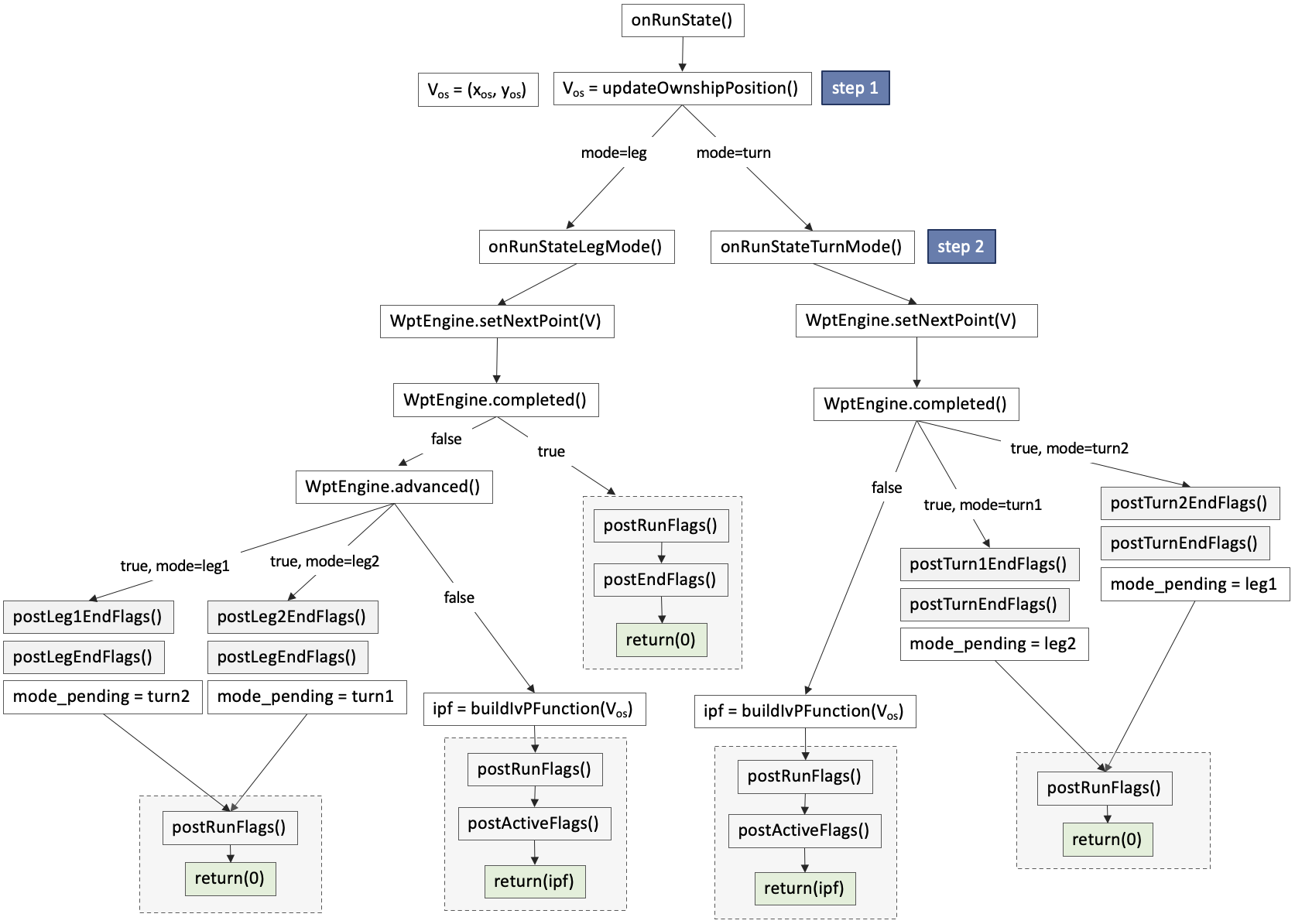
Figure 2.4: LegRun Behavior Loop Flow Chart: Each iteration of the LegRun behavior will proceed through the steps shown, with branching determined by sensed events and the behavior configuration. Details of each step are discuss in their own sections as indicated.
2.3 Construction of the IvP Objective Function [top]
external to the LegRun behavior.
2.4 Active Participation of the LegRun Behavior [top]
In step 15, the LegRun behavior will actively participate in the Helm decision stage by producing IvP function. When a running behavior does indeed produce an objective function, this behavior is said to be in the active state. Both the run flags and active flags will be posted if the user has configured any. Again, the only unique components of these flag postings for the LegRun behavior are the macros supported for solely for the LegRun behavior described in Section N.
Performance Metrics [top]
2.5 Configuration Parameters [top]
Certain configuration parameters available to LegRun behavior are are unique to the LegRun behavior and others are inherited from the IvPBehavior superclass. Here parameters unique to the LegRun behavior are presented.
The set of configuration parameters is long, and split into two groups. The first group deals mainly with the shape of the leg, including position, angle, length and nature of the Williamson turn. The LegRun behavior maintains an instance of a LegRun C++ class, and these parameters are essentially passed directly to that class. The remainder of the configuration parameters relate to the operation of the behavior.
Listing 2.1 - Configuration Parameters for the LegRun Behavior (Leg Shape).
| Parameter | Description |
| p1: | The location of one end of the primary leg. Section ???. |
| p2: | The location of the other end of the primary leg. Section ???. |
| leg: | A specification of the leg given by the leg center point, the angle and the length (rather than the two end points explicitly with the p1 and p2 parameters. |
| leg_len: | The length of the primary legrun track line may be dynamically set to the given value. The center and orientation of the legrun track will be retained, but new locations for the two vertices will be calculated. |
| leg_len_mod: | The length of the primary legrun track line may be dynamically modified by the given value. The center and orientation of the legrun track will be retained, but new locations for the two vertices will be calculated. The new length of the leg cannot be lower than the value set by leg_length_min. |
| leg_len_min: | A minimum leg length is enforced when dynamically adjusting the leg length with the leg_length_mod parameter. This min length is 50 meters. This can be changed with this parameter, but cannot be set lower than 5 meters. |
| leg_ang: | The angle of the primary legrun track line may be dynamically set to the given value. The center and length of the legrun track line will be retained, but new locations for the two vertices will be calculated. |
| leg_ang_mod: | The angle of the primary legrun track line may be dynamically modified by the given value. The center and length of the legrun track line will be retained, but new locations for the two vertices will be calculated. |
| shift_pt: | A location in the x-y plane. If provided, it will override the p1 and p2 parameters and move the primary leg to be centered at the shift_pt, keeping the original primary leg length and angle. |
| turn_bias | The bias value, [-100,100], may be adjusted with this parameter affecting the turn shape at both vertices. A value of -100 will result in a Williamson turn with its longest end aligned with the legrun track line (recommended). The default value is 0. |
| turn1_bias | The bias value, [-100,100], may be adjusted with this parameter affecting the turn shape at vertex 1. A value of -100 will result in a Williamson turn with its longest end aligned with the legrun track line (recommended). The default value is 0. |
| turn2_bias | The bias value, [-100,100], may be adjusted with this parameter affecting the turn shape at vertex 2. A value of -100 will result in a Williamson turn with its longest end aligned with the legrun track line (recommended). The default value is 0. |
| turn1_bias_mod | The bias value for the turn as vertex 1, may be dynamically adjusted with this parameter, during run time, affecting the turn shape at vertex 1. The given value will be added to the existing value. The resulting value will be clipped to the range [-100,100]. |
| turn2_bias_mod | The bias value for the turn as vertex 1, may be dynamically adjusted with this parameter, during run time, affecting the turn shape at vertex 2. The given value will be added to the existing value. The resulting value will be clipped to the range [-100,100]. |
| turn_bias_mod | The bias value for the turn as vertex 1, may be dynamically adjusted with this parameter, during run time, affecting the turn shape at both vertices. The given value will be added to the existing value. The resulting value will be clipped to the range [-100,100]. |
| turn_dir: | The turn direction, "port" or "starboard", the vehicle will turn around both vertices. Acceptable parameter values are "port", "starboard", "star", or "toggle". The default is "star". |
| turn1_dir: | The turn direction, "port" or "starboard", the vehicle will turn around the first vertex. Acceptable parameter values are "port", "starboard", "star", or "toggle". The default is "star". |
| turn2_dir: | The turn direction, "port" or "starboard", the vehicle will turn around the second vertex. Acceptable parameter values are "port", "starboard", "star", or "toggle". The default is "star". |
| turn1_ext | An additional distance, applied beyond the distance of the track leg on turn 1, before the vehicle begins its turn. See Section ???. The default value is 0. |
| turn2_ext | An additional distance, applied beyond the distance of the track leg on turn 2, before the vehicle begins its turn. See Section ???. The default value is 0. |
| turn_ext | An additional distance, applied beyond the distance of the track leg on both ends, before the vehicle begins its turn. See Section ???. The default value is 0. |
| turn1_ext_mod | Modify the turn 1 extent, an additional distance, applied beyond the distance of the track leg on turn 1, before the vehicle begins its turn. See Section ???. The default value is 0. |
| turn2_ext_mod | Modify the turn 2 extent, an additional distance, applied beyond the distance of the track leg on turn 2, before the vehicle begins its turn. See Section ???. The default value is 0. |
| turn_ext_mod | For both turns, modify the turn extent, an additional distance, applied beyond the distance of the track leg on both ends, before the vehicle begins its turn. See Section ???. The default value is 0. |
| tur1_rad | The turn radius of the turn following vertex 1. Any positive value is allowed (yes, any, be carefull), and the default is 15 meters. |
| turn2_rad | The turn radius of the turn following vertex 2. Any positive value is allowed (yes, any, be carefull), and the default is 15 meters. |
| turn_rad | The turn radius of the turn following both vertices. Any positive value is allowed (yes, any, be carefull), and the default is 15 meters. |
| turn_rad_min | A minimum turn radius is enforced when dynamically adjusting the turn radius with the turn*_rad_mod parameters. This min radius is 5 meters. This can be changed with this parameter, but cannot be set lower than 2 meters. |
| turn1_rad_mod | The turn radius of the turn at vertex 1 may be modified with this parameter. It cannot be set lower than the value of turn_rad_min. |
| turn2_rad_mod | The turn radius of the turn at vertex 2 may be modified with this parameter. It cannot be set lower than the value of turn_rad_min. |
| turn_rad_mod | The turn radius of the turn at both vertices may be modified with this parameter. It cannot be set lower than the value of turn_rad_min. |
| turn_pt_gap: | The distance between points comprising the Williamson turns on both ends. The default is 25 meters. Section ???. |
Listing 2.2 - Configuration Parameters for the LegRun Behavior (Leg Shape).
| Parameter | Description |
| capture_line: | When set to true, the behavior will regard a vertex as captured, if it crosses the line at the vertex perpendicular to the trackline. The default is false. |
| capture_radius: | The radius to the target vertex within which the vehicle must arrive for a vertex to considered reached, or captured. The default value is 3 meters. |
| init_leg_mode: | tbd. |
| lead: | For trackline following during the legrun phase of this behavior, this parameter affects the severity of adjustment back to the trackline when there is a trackline error. The default value is 0, meaning no trackline error adjustment will be made. |
| lead_damper: | When adjusting for trackine errors, this parameter will automatically reduce the trackline adjustments the closer the vehicle gets to the trackline. The default value is 0. |
| leg_spds: | A schedule of speeds in m/s to be executed on each successive leg run. |
| leg_spds_onturn: | If set, use this speed, in m/s on turns at the end of each leg run. |
| leg_spds_repeat: | If true, and a schedule of speeds is provided with the leg_spds parameter, then repeat the schedule once it has been exhausted. |
| leg_flag: | A flag to be published on each helm interation while the behavior is the mode of traversing either direction of teh leg. Section ???. |
| leg_endflag: | A flag to be published at the end of each leg as the behavior transitions from either the leg1 mode into the turn1 mode, or from the leg2 mode into the turn2 mode. Section ???. |
| leg1_endflag: | A flag to be published as the behavior transitions from the leg1 mode into the turn1 mode. Section ???. |
| leg2_endflag: | A flag to be published as the behavior transitions from the leg2 mode into the turn2 mode. Section ???. |
| mid_leg_flag: | A flag to be published at a mid point position during the leg. The location of the mid point is determined by the mid_leg_pct parameter. |
| mid_leg_pct: | The percentage [0,100] of the primary leg, at which the behavior after first exceeding this point, will post any configured mid_leg_flag postings. |
| mid_turn_flag: | A flag to be published at a mid point position during a turn. The location of the mid point is determined by the mid_turn_pct parameter. |
| mid_turn_pct: | The percentage [0,100] of turn, at which the behavior will post any configured mid_turn_flag postings. |
| patience: | A patience parameter in the range of [1,99] may be set to adust the relative weight between adjusting speed while maintaining course, or adjusting course while maintaining speed. The default value is 50. |
| slip_radius: | A radius to the target vertex within which the vehicle will declare arrival as soon as the distance to the vertex begins to grow larger. The default value is 15 meters. |
| speed: | The default speed in m/s if no schedule of speed is provided with the leg_spds parameter, or when the speed schedule has been exhausted with no leg_spds_repeat enabled. |
| wpt_status_var: | The name of a MOOS variable to publish a status report. |
| repeat: | The number of times the trackline leg will be repeated before this behavior completes. The default values is 0, meaning it will repeat endlessly. (check this) |
| turn_endflag: | A flag to be published at the end of each leg as the behavior transitions from either the turn1 mode into the leg2 mode, or from the turn2 mode into the leg1 mode. Section ???. |
| turn1_endflag: | A flag to be published as the behavior transitions from the turn1 mode into the leg2 mode. Section ???. |
| turn2_endflag: | A flag to be published as the behavior transitions from the turn2 mode into the leg1 mode. Section ???. |
| visual_hints: | Settings for the posted visual artifacts of this behavior, includeing edge and vertex colors and sizes. See the example configuration block for supported parameters. |
Listing 2.3 - Example Configuration Block.
[[#lst_bhv_trail_ex]]
 Behavior = BHV_LegRun
 {
   name      = legs
   pwt       = 100
   condition = DEPLOY = true
   endflag   = RETURN = true

   updates    = LEG_UPDATE
   perpetual  = true

             lead = 5
      lead_damper = 1
            speed = 4.0   // meters per second
     capture_line = true
   capture_radius = 2
      slip_radius = 15

               p1 = 70, -35
               p2 = -35, -85
           repeat = 1

        turn1_dir = port
        turn2_dir = star
        turn1_rad = 20
        turn2_rad = 20
       turn1_bias = 100
       turn2_bias = 100

      mid_leg_pct = 10
     mid_leg_flag = ZIGGING=true

     visual_hints = nextpt_color=yellow
     visual_hints = nextpt_vertex_size=8
     visual_hints = nextpt_lcolor=gray70
     visual_hints = vertex_color=dodger_blue, edge_color=white
     visual_hints = vertex_size=6, edge_size=1
     visual_hints = turn_edge_color=white
     visual_hints = turn_vertext_color=green
     visual_hints = turn_label_color=off
 }
2.6 Publications [top]
Listing 2.4 - Configuration Parameters for the LegRun Behavior.
| Variable | Description |
| LR_MODE: | The current mode, leg1, leg2, , turn1, turn2. Section ???. |
| LR_MODE_REPORT: | The current mode, vehicle name, and timestamp, to be sent to other vehicles for coordination. |
| LR_TCOORD_SPD: | The speed currently the target speed for the behavior based on its relative position to other vehicles. Only relevant when turn coordination is enabled between multiple vehicles. |
| LR_NOW_SPD: | The speed currently the target speed for the behavior based on its relative position to other vehicles. |
| LR_OS_DEGS: | The position of ownship, in degrees, on the reference circle used when multi-vehicle coordinatio is enabled. |
3 The Waypoint Engine
A WaypointEngine is a C++ utility for behaviors reasoning about waypoints. This capability is isolated in its own utility class so it can be easily put to use in a uniform manner by at least the following behaviors.
- The Waypoint Behavior
- The LegRun Behavior
- The AndersonTurn Behavior
- The WilliamsonTurn Behavior
Core Data Structure and State [top]
The primary data held by the WaypointEngine is simply an ordered list of waypoints, stored in local x-y coordinates:


Figure 3.1: Ordered Set of Waypoints: The primary data of the WaypointEngine is an ordered list of points
The WaypointEngine keeps track of which waypoint is next, which presumably is the waypoint that ownship will be aspiring to reach. Since the WaypointEngine is agnostic to how it may be used within a behavior, or even if the behavior is actively participating in the helm, the notion of the "next" waypoint may or may not reflect the observable trajectory of the vehicle. This value is given by:

Updating the Waypoint Engine [top]
The waypoint engine is periodically updated with a new position of ownship, presumably as ownship is moving toward the next waypoint. This operation is:

This operation will evaluate ownship position relative to the next waypoint,  , and determine if this point has been reached. If so, it will increment
  . If the reached waypoint was the final waypoint, then
  is reset to zero.
After each update, the waypoint engine will calculate three new states based on the new ownship positions. The first state reflects whether a waypoint has been reached upon the most recent update of ownship position. This is true simply if the index  has advanced:

The next state reflects whether a waypoint has been reached upon the most recent update of ownship position, and if the reached waypoint was the final waypoint, En-1

Note in the case where Ecyc is true, this means that ownship has reached the final waypoint, and  has been reset to zero. The waypoint engine can be configured to treat the arrival at the last point as final, or simply a cue to begin proceeding back around to the first point. If it is final, then we say that Ecomp is true.
The Waypoint Steering Point [top]
Enp = xnp, ynp = pE_I
Esp = xsp, ysp
E(P) Initializes the Waypoint Engine with new points
E(PSTR) Initializes the Waypoint Engine with new given by a string
 ,
,  Distance of ownship to the next waypoint
Ed' Previous distancd of ownship to the next waypoint, reset to -1 when a waypoint is advanced.
3.1 Flags and Macros [top]
3.2 Flags and Macros [top]
The LegRun behavior supports the below set of event flags in addition to the standard behavior flags, e.g., endflags, runflags. These are:
- leg_end_flag: Posted when the vehicle reaches the end of the leg, regardless of the direction.
- leg1_end_flag: Posted when the vehicle reaches the end of leg1, i.e., the leg traversing from P2 to P1.
- leg2_end_flag: Posted when the vehicle reaches the end of leg2, i.e., the leg traversing from P1 to P2.
- mid_leg_flag: Posted when the vehicle has partially traversed the main leg, in either direction. The point where it is posted is determined by the mid_leg_pct parameter.
- mid_turn_flag: Posted when the vehicle has partially traversed a turn, in either direction. The point where it is posted is determined by the mid_turn_pct parameter.
- turn_end_flag: Posted when the vehicle reaches the end of a turn, regardless of the direction.
- tur1_end_flag: Posted when the vehicle reaches the end of turn1, i.e., the turn traversing from P1 to P2.
- turn2_end_flag: Posted when the vehicle reaches the end of turn2, i.e., the turn traversing from P2 to P1.
The following macros are supported in the LegRun behavior. These macros will be expanded in any event flag, including event flags defined for all IvP behaviors as well as event flags defined only for the LegRun behavior.
- CORE_POLY: The specification of the polygon representing the core operation area.
- SAVE_POLY: The specification of the polygon representing the operation area, outside which the vehicle will actively attempt to return to.
- HALT_POLY: The specification of the polygon representing the halt area, outside which the vehicle will post an emergency all-stop message.
Document Maintained by: mikerb@mit.edu
Page built from LaTeX source using texwiki, developed at MIT. Errata to issues@moos-ivp.org. Get PDF