Lab 6 - SeaBeaver III Tailcone Assembly
1 Overview and Objectives
2 What you need to know before you start
2.1 Waterproof, high-pressure seals
2.2 Components of the Tailcone
3 Step A - Preparing the Tailcone Pressure Hull for Assembly
4 Step B - Installing the Blank Penetrator
4.1 Cleaning a penetrator and O-ring
4.2 Greasing a penetrator and O-ring
4.3 Cleaning the face of the bulkhead
4.4 Installing the penetrator
5 Step C - Installing the Pressure Sensor
6 Step D - Installing the Thruster Mount onto the Pressure Hull
6.1 Mounting the Thruster onto the Thruster Mount
6.2 Installing the thruster cable penetrator
6.3 Installing the thruster mount
7 Step E - Installing the Mast onto the Pressure Hull
8 Step F - Installing Rotary Seal Penetrators
9 Step G - Installing the Servo
9.1 Installing the servos onto their servo mounts
9.2 Installing the servo shaft coupler
9.3 Installing the coupling collar
9.4 Installing servo mounts onto the pressure hull
10 Step H - Installing the Flange
10.1 Cleaning and greasing the face O-ring
10.2 Installing the flange into pressure hull
11 Step I - Installing the Switch
12 Step J - Installing the Charging and Vacuum Ports
13 Step K - Installing Fins
1 Overview and Objectives
- Learning how to assemble and seal pressure hulls to withstand external high-pressure
- Learning how to install cable penetrators through a pressure hull
- Learning how to install O-rings to create a high-pressure seal
2 What you need to know before you start
The tailcone is one of the most critical parts of the AUV. In the SeaBeaver III design, the tailcone houses the actuators that drive and maneuver the vehicle. This complex part contains several cable penetrators, three rotary seals, and one o-ring flange. Because of this, the tailcone has many delicate surfaces---so you will need to handle its components with extra care until the tailcone assembly is complete.
2.1 Waterproof, high-pressure seals [top]
The SeaBeaver III AUV is designed to operate at depths of up to 60 meters. However, improper installation of seals can lead to immediate water ingress or cause the vehicle to fail at significantly shallower depths. It is therefore essential to take great care and follow instructor guidelines properly when installing all seals and o-rings to ensure that the vehicle remains watertight under pressure.
When the tailcone is fully assembled, it is generally safe from rough external handling. However, before the assembly, there are areas that are extremely delicate, and should not be damaged:
- Any uncovered O-rings
- Any surfaces that comes in contact with the O-rings when it is assembled (see Figure 2.1).
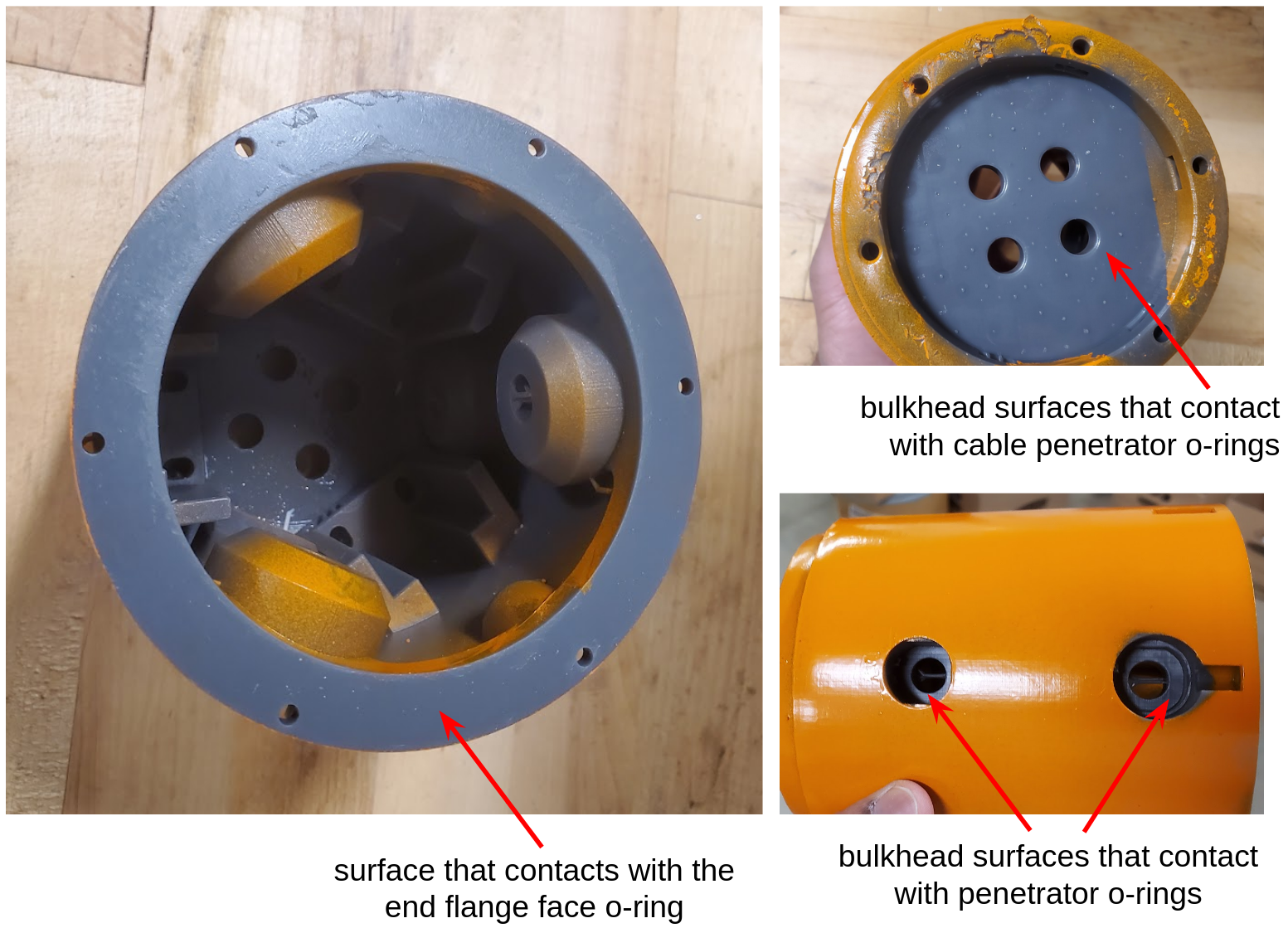
Figure 2.1: These surfaces contact with face O-rings; therefore they must be smooth without any cracks or damages.
2.2 Components of the Tailcone [top]
The tailcone assembly consists of several components, and it is helpful to be familiar with their names. Figure 2.2 labels the different components using the terminology we will use throughout this guide.
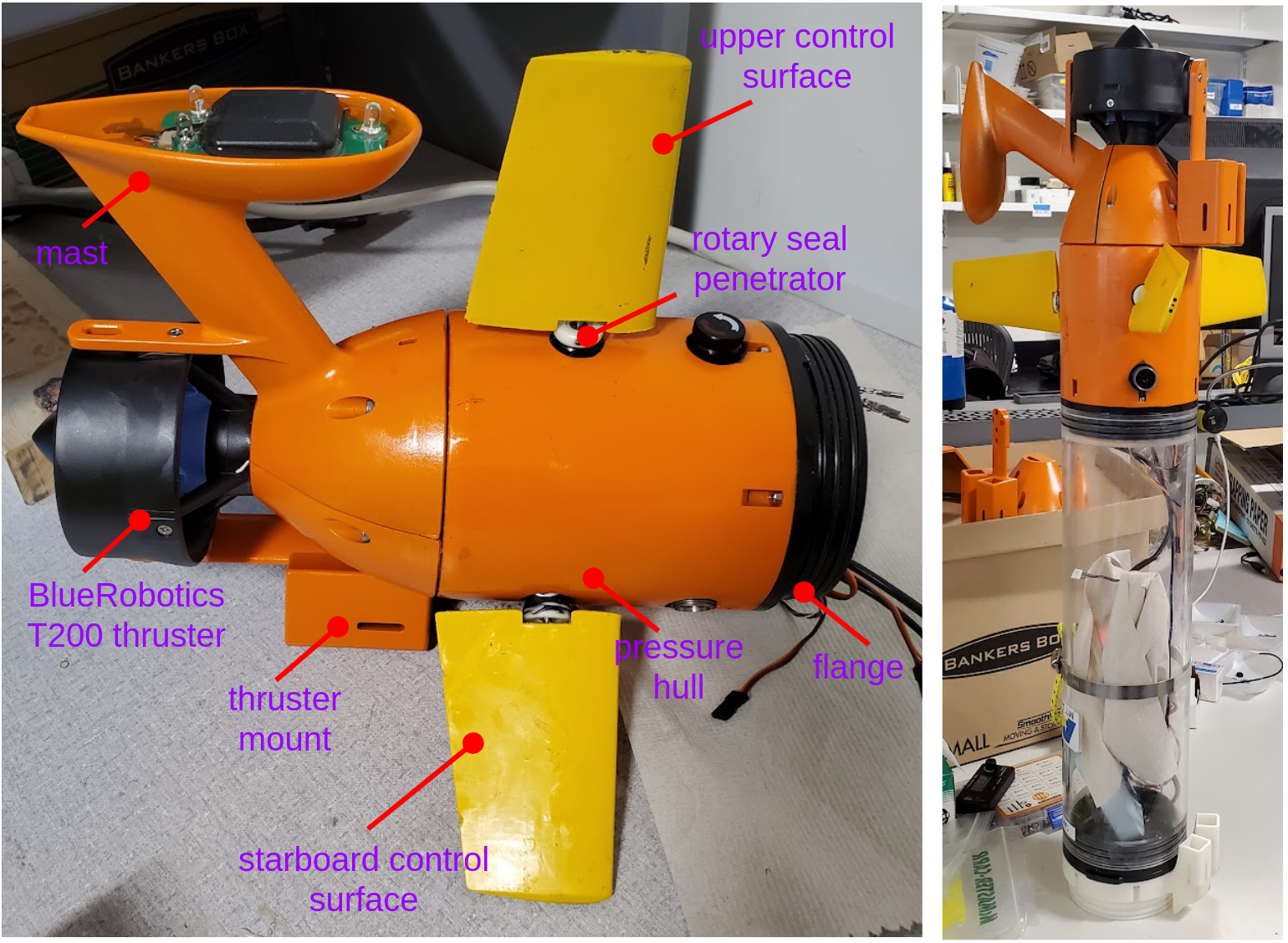
Figure 2.2: Component names of the tailcone assembly
3 Step A - Preparing the Tailcone Pressure Hull for Assembly
The pressure hull is a 3D-printed component. While 3D printing offers significant advantages in rapid prototyping and manufacturing, it often leaves surface artifacts from support structures -- printed part must be properly post-processed as to achieve a suitable surface finish. Therefore, the following post-processing steps should be performed by you before starting the assembly:
- The surfaces that comes in contact with O-rings should be carefully sanded by hand (using a sandpaper that has a FePA grit value above P800). These surfaces are shown in Figure 2.1.
- Artifacts may be present inside the holes designed for the penetrators, potentially making it difficult to insert them properly. These artifacts must be carefully removed, taking special care not to damage the surfaces that interface with the penetrator face O-ring. To verify this, insert a blank penetrator into each hole and check for any obstructions. If any artifacts are detected, talk to an instructor for assistance.
- Test fit both the mast and the thruster mount against the pressure hull to ensure that they sit flush, without any visible gaps. If there is a gap, you may need to sand the face shown in Figure 3.1 that comes in contact with the mast and thruster mount.
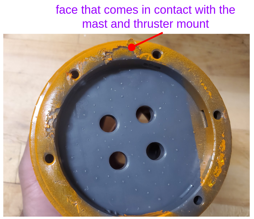
Figure 3.1: You may need to sand this face in order to ensure that both the mast and the thruster mount sits flush against pressure hull
4 Step B - Installing the Blank Penetrator
The aft bulkhead of the pressure hull has four slots for four cable penetrators. They are dedicated for the following:
- Cable of the BlueRobotics T200 thruster
- Cable of the mast
- Pressure (depth) sensor
- An unused blank slot reserved for future upgrades
Installing the blank penetrator and the depth sensor first makes the rest of the installation process a bit easier.
4.1 Cleaning a penetrator and O-ring [top]
When cleaning the O-ring with a Kimwipe blotted with methyl alcohol, carefully inspect it for any dirt, dust, or cuts, as these can significantly compromise the quality of the seal. Avoid stretching the O-ring during cleaning or when applying grease, as this may deform its shape and reduce sealing performance.
Figure 4.1: The groove of the penetrator and the O-ring must be well cleaned with Methyl Alcohol before greasing video:(0:01): https://vimeo.com/1076088353
4.2 Greasing a penetrator and O-ring [top]
While greasing the O-ring, gently run your fingertips along its surface to check for any cuts, scratches, or irregularities. These small defects can be difficult to see but may compromise the integrity of the seal.
Figure 4.2: A thin film of O-ring grease should be carefully applied to the O-ring and the groove of the penetrator video:(0:01): https://vimeo.com/1076090192
4.3 Cleaning the face of the bulkhead [top]
Thoroughly clean the face of the bulkhead and apply a thin, even layer of O-ring grease. Ensure that the surface is completely free of dirt, dust, and any irregularities such as scratches or cuts, as these can prevent a proper seal and compromise the water-tightness of the vehicle.
Figure 4.3: The face of the bulkhead must be cleaned and greased before installing the penetrator video:(0:01): https://vimeo.com/1076072502
4.4 Installing the penetrator [top]
Apply a few drops of Loctite Threadlocker Blue onto the threads of the penetrator to prevent the nut from loosening over time due to vibration. Before applying the threadlocker, clean the threads thoroughly using alcohol wipes to ensure proper adhesion. Take extra care not to get any Loctite on the O-ring or the bulkhead face, as this could compromise the sealing surface.
Figure 4.4: The blank penetrator is installed to the aft bulkhead using a serrated flange nut video:(0:01): https://vimeo.com/1076101141
5 Step C - Installing the Pressure Sensor
Similar to the blank penetrator, install the pressure sensor carefully. The pressure sensor cable is particularly fragile, so take extra caution not to pinch or snip it while tightening the nut.
Figure 5.1: Installing the depth sensor to the aft bulkhead. Don't forget to apply loctite to the threads! video:(0:01): https://vimeo.com/1076093653
6 Step D - Installing the Thruster Mount onto the Pressure Hull
Mounting the thruster is a three-step process. First, the thruster is secured to the thruster mount. Next, the thruster’s cable penetrator is installed onto the pressure hull. Finally, the entire thruster mount assembly is attached to the pressure hull, completing the installation.
6.1 Mounting the Thruster onto the Thruster Mount [top]
Use the provided M3 screws to attach the thruster to the thruster mount. If your thruster is brand new, you may need to remove the back cover in order to access the mounting holes.
Figure 6.1: Mounting the thruster onto the thruster mount using M3 screws video:(0:01): https://vimeo.com/1076105538
6.2 Installing the thruster cable penetrator [top]
Following the same steps used for the blank penetrator and depth sensor installation, install the thruster cable penetrator onto the pressure hull bulkhead.
Figure 6.2: Installing the thruster cable penetrator video:(0:01): https://vimeo.com/1076105989
6.3 Installing the thruster mount [top]
The thruster mount is attached to the pressure hull using square nuts and screws. As shown in Figure 6.3, insert the square nuts into their designated slots. To prevent the nuts from falling during assembly, it may be helpful to apply a small amount of ``monkey poop" (tar) to temporarily hold them in place until the screws are fully tightened.
Figure 6.3: Installing the thruster mount onto the pressure hull video:(0:01): https://vimeo.com/1076104991
7 Step E - Installing the Mast onto the Pressure Hull
Similar to the thruster mount, begin by installing the mast cable penetrator onto the pressure hull. Before mounting the mast itself, remove the top screw from the T200 thruster -- this screw will later be used to secure the mast in place, providing additional structural strength once the mast is mounted onto the pressure hull and the thruster.
Figure 7.1: Installing the mast onto the pressure hull video:(0:01): https://vimeo.com/1076103507
8 Step F - Installing Rotary Seal Penetrators
Installing the rotary seal penetrator is similar to installing a penetrator onto the aft bulkhead. First, ensure that the face of the pressure hull is thoroughly cleaned using alcohol wipes, and inspect it for any damage. The pressure hull's slot for the rotary seal is specifically designed to hold the penetrator in place without turning, which helps when screwing the nut to secure the penetrator. Be sure to apply Loctite Threadlocker Blue onto the threads to prevent the nut from loosening over time.
Figure 8.1: Installing rotary seal penetrators video:(0:01): https://vimeo.com/1076091710
9 Step G - Installing the Servo
SeaBeaver III AUVs are equipped with three servo motors that actuate the vehicle’s control surfaces. While conventional AUV tailcone designs often rely on gear wheels to transfer torque from the servo motors to the control surface shafts, the SeaBeaver features a unique design that allows the servo motors to be aligned inline with the control surface shafts, enabling direct-drive actuation. As shown in Figure 9.1, the servo motors are mounted with a 5 mm offset from each other along the longitudinal axis. This staggered arrangement allows the drive shafts to pass one another without interference, allowing direct drive actuation.
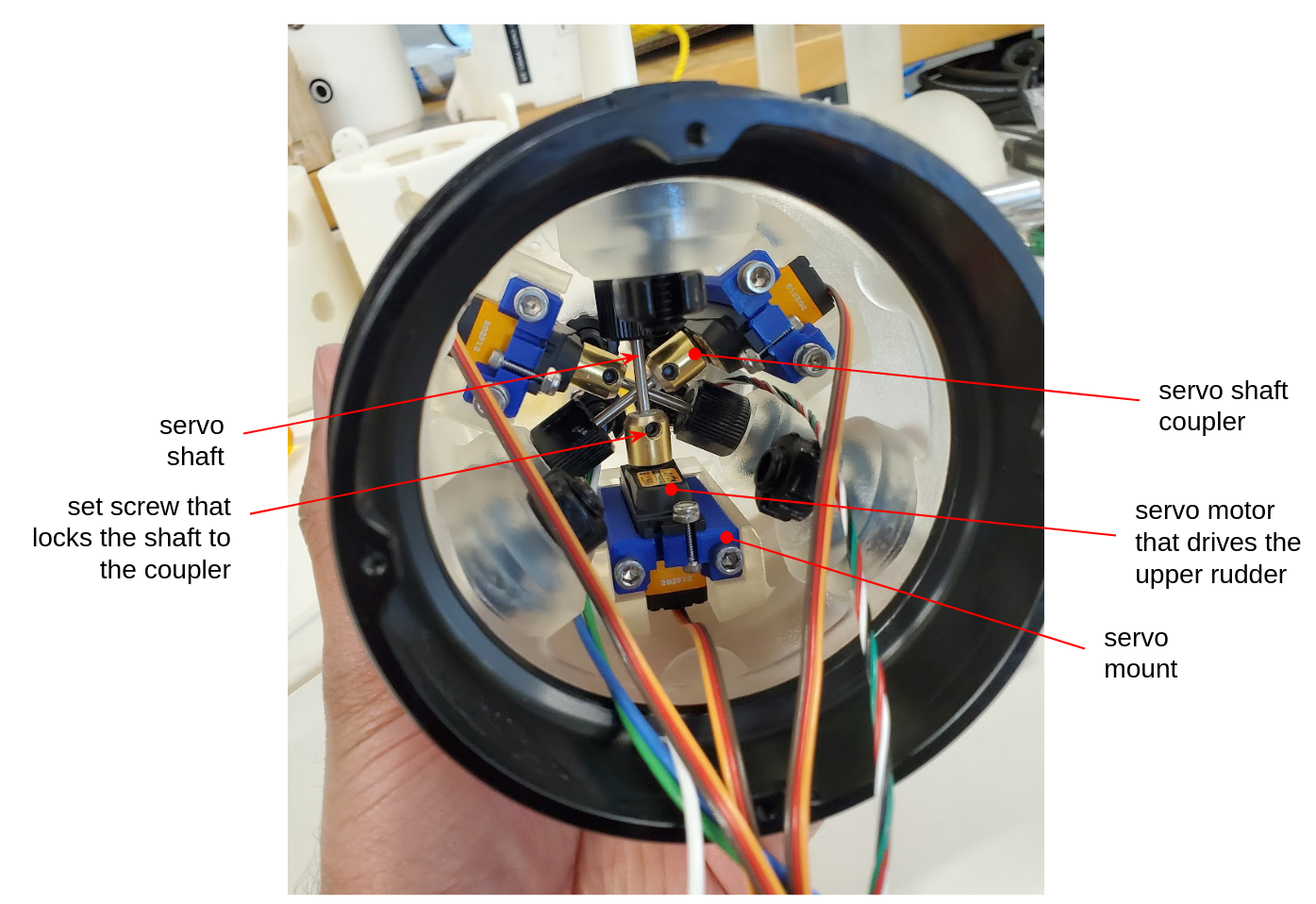
Figure 9.1: The three servo motors are mounted with an offset in the longitudinal axis, enabling direct-drive actuation
9.1 Installing the servos onto their servo mounts [top]
As shown in Figure 9.2, the three servo motors should first be attached to the servo mounts using the provided screws and nuts.
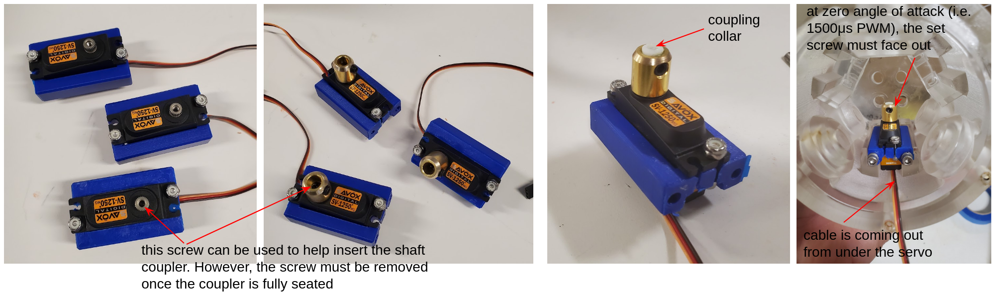
Figure 9.2: The three servo motors are mounted with an offset in the longitudinal axis, enabling direct-drive actuation
9.2 Installing the servo shaft coupler [top]
The next step is to install the servo shaft coupler. This should be done while the servo motor is powered and set to its zero position (i.e., 1500 microsecond PWM signal). When installing the shaft coupler, ensure that the set screw will be facing outward once the assembly is mounted onto the pressure hull. Refer to Figure 9.2 for guidance on orientation.
9.3 Installing the coupling collar [top]
The coupling collar (shown in Figure 9.2) is used to securely fasten the control surface shaft to the shaft coupler. It is recommended to install the collar before mounting the servo assembly onto the pressure hull, as this makes the process easier. Use the set screw to secure the collar in place.
Figure 9.3: Installing the servo onto the servo mount video:(0:01): https://vimeo.com/1076104051
9.4 Installing servo mounts onto the pressure hull [top]
The square nuts should first be inserted into their designated slots. Then, use the provided screws to secure the servo mounts to the square nuts. Be sure to include 2–3 washers as needed to ensure a proper fit and alignment. It is often easier to install the innermost servo first before proceeding with the others.
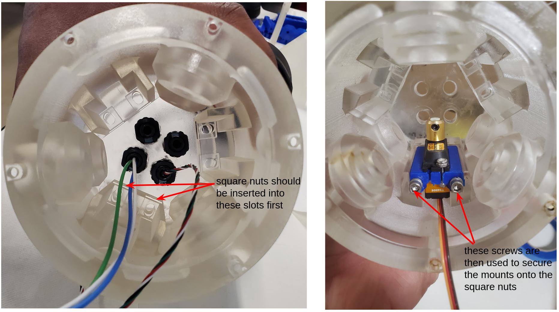
Figure 9.4: The square nuts should first be inserted into their designated slots. Then, use the provided screws to secure the servo mounts to the square nuts.
Figure 9.5: Installing the servo mount onto the pressure hull video:(0:01): https://vimeo.com/1076104609
10 Step H - Installing the Flange
10.1 Cleaning and greasing the face O-ring [top]
When cleaning the O-ring with a Kimwipe blotted with methyl alcohol, take care to inspect it thoroughly for any dirt, dust, or cuts, as these can significantly reduce the quality of the seal. Be cautious not to stretch the O-ring while cleaning or applying grease, as stretching can deform its shape and negatively impact its sealing performance. While greasing the O-ring, gently run your fingertips along its surface to feel for any cuts, scratches, or irregularities. These small defects might not always be visible but can severely compromise the integrity of the seal.
Figure 10.1: Cleaning and greasing the face O-ring of the flange video:(0:01): https://vimeo.com/1076073326
10.2 Installing the flange into pressure hull [top]
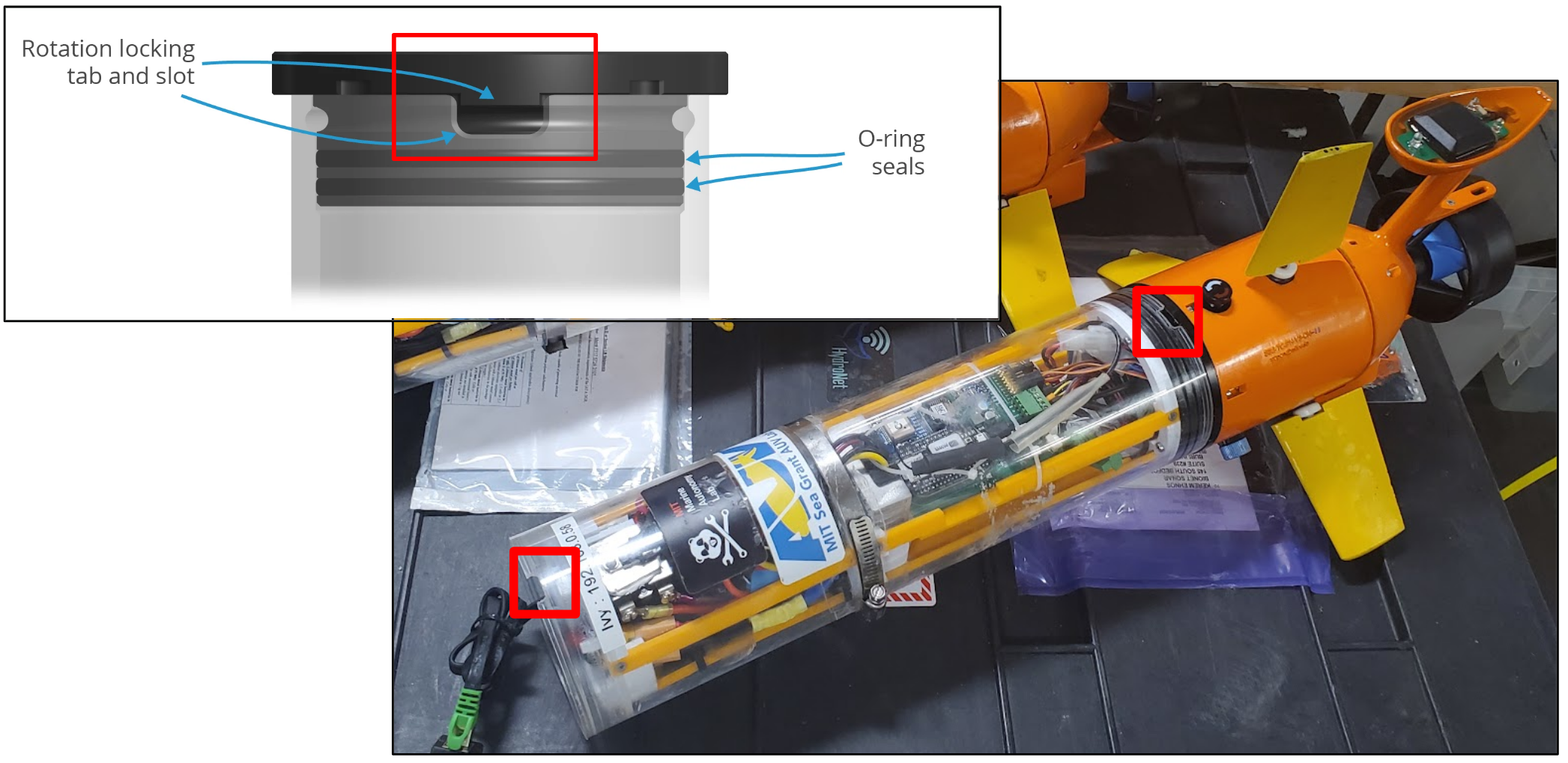
Figure 10.2: The rotation locking tab on the flange that corresponds to the slot in the bottle should face upwards
Before installing the flange, clean and grease the face of the pressure hull to ensure a proper seal. The flange has a rotation locking tab that corresponds to a slot in the BlueRobotics bottle. In the SeaBeaver design, this tab should face upwards (See Figure 10.2). Use M3 screws of the correct length to secure the flange onto the pressure hull. If your pressure hull is Version 3.0 or earlier, it is especially important to take extra care not to strip the threads while tightening the screws. Avoid applying lateral force to the screw, as this can cause the threads to strip. Always tighten the screws carefully and in a consistent, straight direction to ensure a secure fit and prevent damage to the pressure hull.
Figure 10.3: Installing the flange onto the pressure hull video:(0:01): https://vimeo.com/1076096655
11 Step I - Installing the Switch
Similar to the rotary seal, installing the switch to the pressure hull involves careful handling to ensure a proper seal and secure installation. Begin by cleaning the face of the pressure hull using alcohol wipes to remove any dirt or debris. Inspect the area for any damage or imperfections before proceeding.
Figure 11.1: Installing the flange onto the pressure hull video:(0:01): https://vimeo.com/1076101867
12 Step J - Installing the Charging and Vacuum Ports
Following the same precautions and steps, install the charging and vacuum ports.
Figure 12.1: Installing the charging and vacumm Ports video:(0:01): https://vimeo.com/1076102796
13 Step K - Installing Fins
The final step in the tailcone assembly process is installing the fins. To create a high-pressure, watertight seal between the pressure hull and the rotary shaft, we use two O-ring-loaded U-Cup Seals. These seals should be carefully inspected for damage and debris before installation. Apply a film of O-ring grease to both sealing surfaces; i.e., the outer surface that contacts the penetrator sleeve and the inner surface that contacts the rotary shaft. Also, ensure the penetrator sleeve is clean and greased.
When installing, make sure the O-rings are facing outward (i.e., water-side).
Once the two O-ring-loaded U-Cup Seals are inserted, install the bearing. This bearing ensures that external forces acting on the fin are transferred to the penetrator--and thus to the pressure hull--rather than to the O-ring-loaded U-Cup Seals. It also protects the seals from external dirt and debris.
Apply a thin layer of grease on the fin shaft, and carefully insert it without damaging the U-Cup Seals. Once the shaft is seated inside the coupling collar of the servo motor, tighten the set screw to secure the fin. Ensure that the fin is rigidly connected to the servo motor.
Figure 13.1: Installing fins video:(0:01): https://vimeo.com/1076095292
Document Maintained by: supun@mit.edu
Page built from LaTeX source using texwiki, developed at MIT. Errata to issues@moos-ivp.org.
 Get PDF