Lab 1 - Introduction to SeaBeaver II AUVs
1 Overview and Objectives
2 SeaBeaver II class AUVs
2.1 SeaBeaver II training-kit
2.2 SeaBeaver II field-kit
3 AUV naming conventions
3.1 Nose-cone
3.2 Tail-cone
3.3 Pressure hull
3.4 Free flood space
3.5 Ballast
3.6 Mast
3.7 Control surfaces
3.8 Six degree of freedom (6-DOF) motion of an AUV
3.9 Nautical terms
1 Overview and Objectives
- Goal 1 - An introduction to the SeaBeaver II training-kit and field-kit
- Goal 2 - Learning name conventions that will be used throughout this class
2 SeaBeaver II class AUVs
SeaBeaver is a low-cost micro AUV design, developed at MIT. We refer to this design as the SeaBeaver class, encompassing all AUVs manufactured using this design. While individual SeaBeaver vehicles may bear different names such as Alpha, Bravo, Charlie, or Little-Mermaid, they all belong to the SeaBeaver AUV class.
The initial iteration of our SeaBeaver design was designated as SeaBeaver I. This version has undergone significant enhancements in electronics, hardware, and software, evolving into SeaBeaver II (see Figure 2.1).
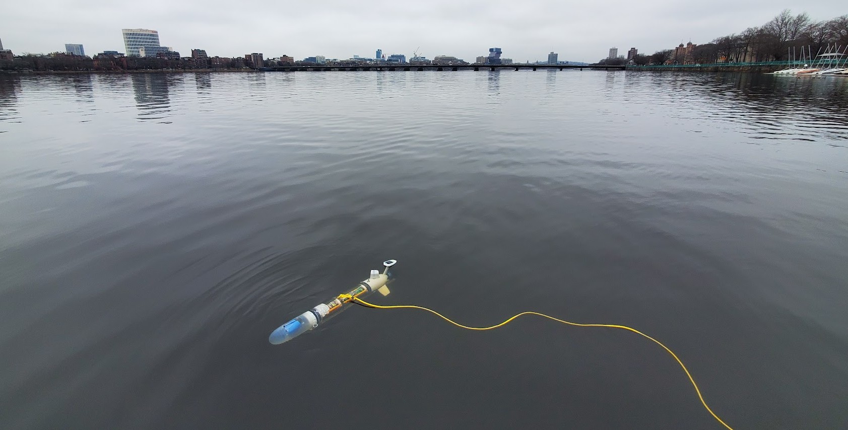
Figure 2.1: Sea trials of the first SeaBeaver II class AUV, SB2-alpha
2.1 SeaBeaver II training-kit [top]
One of the primary objectives of MIT 2.S01 is to familiarize you with the internal components of the AUV and to ensure that you become comfortable with safely working with them. To facilitate this learning process, we have introduced the SeaBeaver II training kit.
As shown in Figure 2.2, the training kit comprises identical electronics and software to those found in the actual vehicle. However, there are two main distinctions between the training kit and the physical AUV:
- The training-kit lacks the tail-cone pressure hull, which houses servo motors that drives control surfaces, the main propulsion thruster, and the mast containing LED indicators and an active GPS antenna. Instead, it is connected to a mock-up tail-cone equipped with servo motors and LEDs, emulating the SeaBeaver tail-cone.
- The training kit does not include the main battery or the power management system. Instead, it offers two alternative power sources: (1) a wall-pluggable power adapter and (2) a compact rechargeable travel battery for mobile exercises.
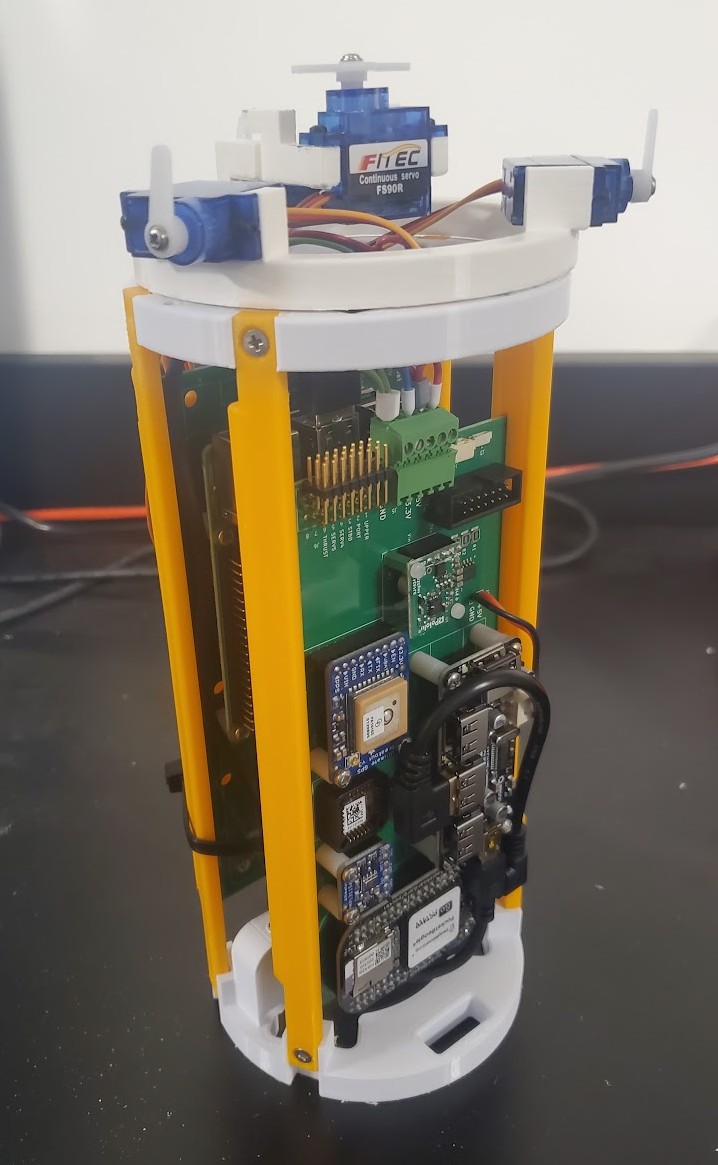
Figure 2.2: SeaBeaver II training-kit
Each of you will receive a training kit to utilize throughout the duration of the 2.S01 class, allowing for hands-on learning experiences both in the classroom and at home.
2.2 SeaBeaver II field-kit [top]
Each training-kit can be paired with a field-kit to assemble a complete vehicle (see Figure 2.3). The field kit comprises the following components:
- Components necessary for constructing a tail-cone pressure hull, including 3D printed parts, the main propulsion thruster, servo motors, control surfaces, rotary seals, flanges, bulkhead connectors, and a potted mast. You will have the opportunity to assemble your tail-cone with our guidance and support.
- A main pressure hull housing along with relevant flanges and bulkhead connectors.
- A nose-cone
- Two ballast rails that allows hydrostatic balancing of the vehicle by adding, removing, or shifting weights.
- The main battery and power management system
Every pair of students will receive a field-kit to facilitate hands-on assemblyand experimentation of their own SeaBeaver class AUV.

Figure 2.3: Parts of the SeaBeaver II field-kit (left); and final assembled AUV by pairing up the training-kit with field-kit (right).
3 AUV naming conventions
3.1 Nose-cone [top]
The nose-cone is the forward end of the AUV (Figure 3.1). In SeaBeaver class AUVs, the nose-cone is a free flood section; functioning as a wet payload bay intended to accommodate sensors that directly interact with the water. These sensors may include external pressure sensors, water temperature sensors, acoustic receiver hydrophones, acoustic transmitter transducers, etc.
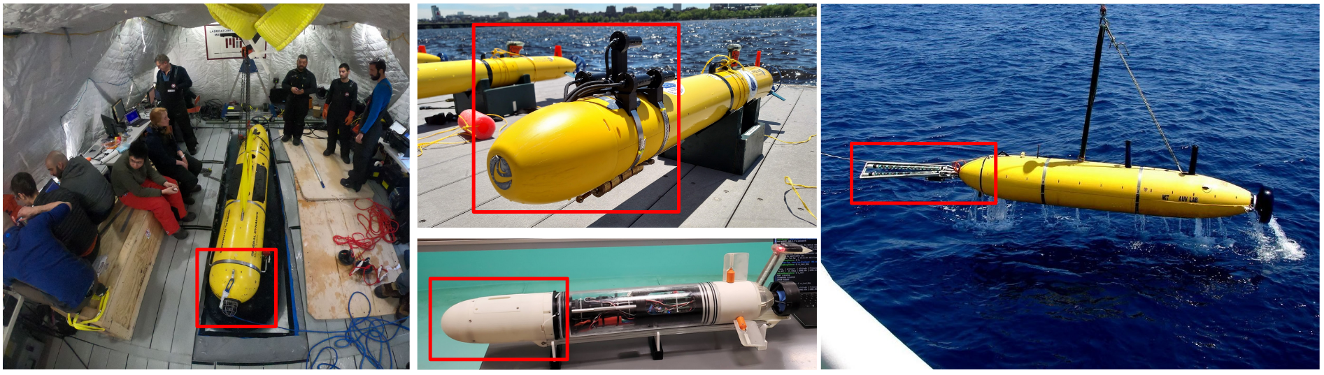
Figure 3.1: Nose-cones of AUVs
3.2 Tail-cone [top]
The tail-cone constitutes the aft end of the AUV (refer to Figure 3.2). Conventionally, it houses the propulsion and control actuator mechanism, such as the thruster(s), control surfaces, and their respective drive mechanisms. In SeaBeaver class AUVs, the tail-cone encompasses three control surfaces along with their servo-based drive mechanisms, the main thruster, mast, and an external pressure/temperature sensor.
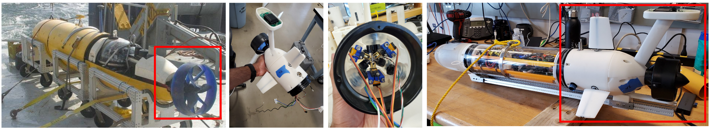
Figure 3.2: Tail-cones of AUVs
3.3 Pressure hull [top]
The pressure hull, also known as the pressure housing or electronics housing, constitutes a dry compartment within the vehicle, primarily designated for housing electronics (refer to Figure 3.3). The internal pressure of this compartment is generally equal to or lower than atmospheric pressure. Consequently, the pressure hull must possess the structural integrity to endure the external water pressure at the vehicle's designated crush depth.
In certain scenarios, the housing is filled with oil. Within oil-filled housings, the internal pressure equals or slightly exceeds the external water pressure. Consequently, the housing's walls do not need to withstand the external pressure, as there are no air cavities present. However, it is imperative that individual components placed within an oil-filled housing can operate effectively at the vehicle's designated crush depth.
3.4 Free flood space [top]
A free flood space refers to an area or compartment where external water can flow freely in and out (refer to Figure 3.3). The boundary walls of such sections essentially act as a fairing, maintaining the hydrodynamic shape of the vehicle. As there are no air cavities present, these fairing walls do not need to withstand external water pressure.
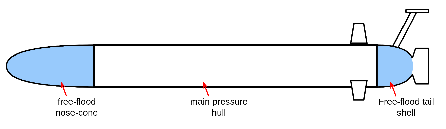
Figure 3.3: Pressure hull and free flood sections of SeaBeaver II AUV class
3.5 Ballast [top]
Ballast refers to heavy materials, typically lead or stainless steel blocks, strategically placed within the vehicle to increase weight or shift its center of gravity (refer to Figure 3.4). As you will learn later in the class, AUVs are usually ballasted to maintain a slight positive buoyancy, where buoyancy slightly exceeds the overall in-water weight. Additionally, they are adjusted to have zero trim and heel angles. This is achieved by adding, removing, and shifting ballast weights (see Figure 3.4).
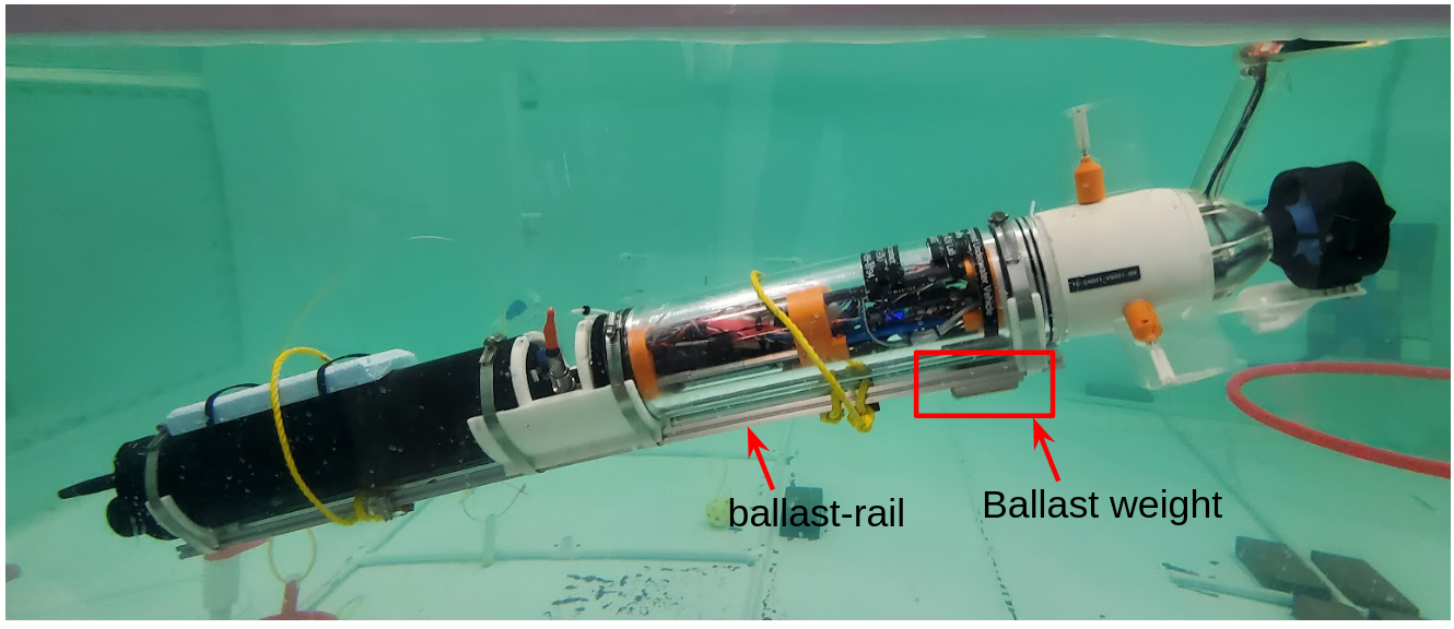
Figure 3.4: Ballasting the SeaBeaver I - echo AUV
3.6 Mast [top]
The mast of an AUV typically accommodates various antennas. These antennas may include a GPS antenna, satellite modem antenna, cellular modem antenna, and WiFi antenna. Additionally, the mast may feature light strobes to enhance the vehicle's visibility when at the surface. Ensuring adequate surface visibility is crucial for AUVs, facilitating easy recovery after a mission. Masts are typically designed to be raised above the waterline to optimize reception and visibility.
3.7 Control surfaces [top]
The control surfaces (a.k.a fins, control planes, rudders/elevators) are used to turn the vehicle in horizontal and vertical planes (i.e. yawing and pitching). Similar to a rudder of a ship, they generate a lift force when they pose an angle of attack to the direction of the flow. This force is used to turn the vehicle.
3.8 Six degree of freedom (6-DOF) motion of an AUV [top]
Figure 3.5 illustrates the 6-DOF motion of an underwater vehicle. There are three axes in an underwater vehicle, called longitudinal, transverse and vertical axes. The motion along and around them are:
- Surge: linear forwards and backwards motion along the longitudinal horizontal axis
- Sway: linear transverse (side-to-side) motion along the transverse (a.k.a lateral) horizontal axis
- Heave: linear vertical (up and down) motion along the vertical axis
- Roll: Angular motion of the vehicle about its longitudinal axis.
- Pitch: Angular motion of the vehicle about its transverse axis.
- Yaw: Angular motion of the vehicle about its vertical axis.
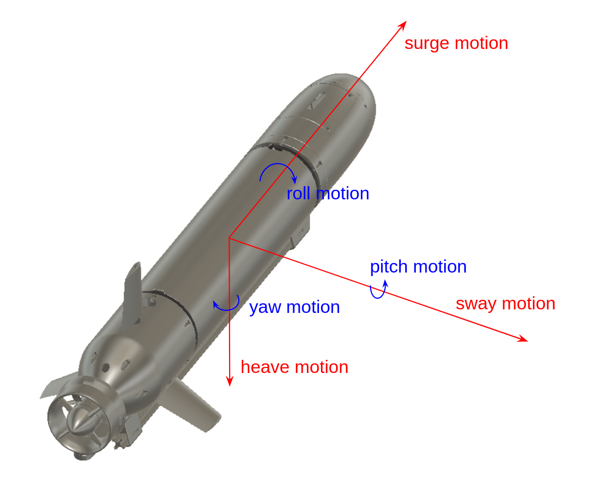
Figure 3.5: Six degree of freedom (6-DOF) motion of an AUV
Steady state offset angles in roll and pitch also have names:
- Heel angle: a steady state roll angle offset due to the ship's own weight distribution.
- Trim angle: a steady state pitch angle offset due to the ship's own weight distribution
3.9 Nautical terms [top]
Additional nautical terms:
- Port: the left of the vehicle as you look forward
- Starboard: the right of the vehicle as you look forward
- Bow: the forward part of the vehicle
- Stern: the rear part of the vehicle
- Forward: towards the front of the vehicle
- Aft: toward the stern of the vehicle
- Waterline: the lines that separates the submerged section of the vehicle from the section above, while the vehicle is at surface
Document Maintained by: supun@mit.edu
Page built from LaTeX source using texwiki, developed at MIT. Errata to issues@moos-ivp.org.
 Get PDF