The OpRegionV24 Behavior
Maintained by: mikerb@mit.edu  Get PDF
src: project-pavlab/bhvdocs/bhv_opregion_v24
1 The OpRegionV24 Behavior
1.1 Intended Mission Use
1.2 The Core Algorithm
1.3 Configuration and Operation Mechanics
1.3.1 Configuring the Polygon Regions
1.3.2 Halt Polygon Triggers
1.3.3 Mission Time, Depth, and Altitude Operation Envelope
1.3.4 Resetting a Breach Condition
1.4 IvP Function Formulation
1.5 Configuration Parameters and Examples
1.6 Flags and Macros
1 The OpRegionV24 Behavior
The OpRegionV24 behavior was created to combine and replace the OpRegion and OpRegionRecover behaviors. The former was simply a pass-fail check to ensure operating constraints are not exceeded, resulting in an all-stop if they were. No attempt was made in the OpRegion behavior to influence the vehicle to avoid exceeding the operating constraints. On the other hand, in the OpRegionRecover behavior, the goal is indeed to influence the vehicle to return to an the operation area once it has exited. The OpRegionV24 behavior can perform both functions of the older behaviors. It works with the notion of three polygons, the core, save and halt polygons shown in Figure 1.1 below.

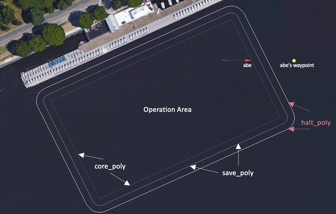
Figure 1.1: OpRegionV24 Behavior Regions: The operation area is defined by the core polygon. The buffer region is defined by the save polygon. The all-stop region is the area outside the halt polygon.
The core polygon is the main operation area, presumably where the mission will be contained under normal circumstances. The save polygon extends the core polygon and once the vehicle is outside this polygon buffer zone, this behavior will begin to produce an objective function influencing the the vehicle back into the save polygon. The halt polygon extends the buffer region even further. If the vehicle breaches the halt polygon, an all-stop will be enforced.
1.1 Intended Mission Use [top]
The OpRegionV24 behavior is typically running in every helm mode of a mission, to guard against exceeding certain safety boundaries. The operation area is one, but there are three other bounds: (1) maximum depth, (2) maximum altitude, and (3) maximum mission time. The first two are only relevant for underwater vehicles, but the maximum mission time is another way to ensure that, if all other safeguards fail, the mission can be halted after a certain duration. For an underwater vehicle that has disappeared, the maximum time can significantly reduce the search box area.
Defining and constraining operation area is the most visual aspect of the OpRegionV24 behavior. As shown in Figure 1.1, three regions or polygons are supported. The core, save, and, halt polygons. The former is simply the area declared to be the intended operation area. Even if there are no hazards around this area, this conveys an important element of the mission plan to the operators and others observing a deployment. The save polygon usually subsumes the core polygon by some buffer distance. This conveys the degree to which deviation from the core area may be tolerated. For vessels that breach the save polygon, the OpRegionV24 behavior will produce an IvP Function to influence the vehicle back within the save polygon. The halt polygon is a final boundary, beyond which the behavior will produce an all-stop message. Figure 1.2 shows the effects of breaching the save and halt polygons.
Figure 1.2: OpRegionV24 Behavior: Left: A vehicle exits the operating area and save polygon buffer zone, and amends its course to return to the the buffer zone. Right: A vehicle exits the buffer zone and is unable to complete a turn before breaching the halt polygon. An all-stop state results.
1.2 The Core Algorithm [top]
The OpRegionV24 behavior may be configured to use none or all of the possible constraints, e.g., (1) max time, (2) max depth, (3) min altitude, (4) halt polygon, or (5) save polygon. The onRunState() algorithm will first check for all the constraints that would result in an all-stop condition. If it passes these, then the vehicle is checked for containment of the save polygon. An IvP function is only generated if the behavior is attempting to return the vehicle to the save polygon.
OnRunState() Flow Chart [top]
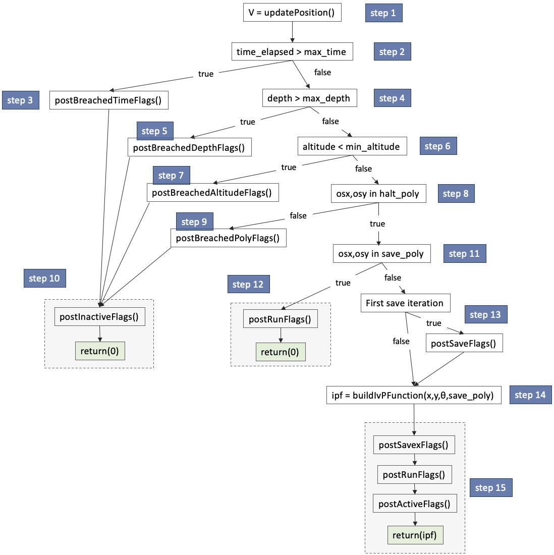
Figure 1.3: OpRegionV24 Behavior Loop Flow Chart: Each iteration of the OpRegionV24 behavior will proceed through the steps shown, with branching determined by sensed events and the behavior configuration. Details of each step are discuss in their own sections as indicated.
OnRunState() Pseudo Code [top]

In Step 1, ownship information is updated, including the ownship local x-y position, heading, speed, and depth if the vehicle is an underwater vehicle, and altitude if the underwater vehicle is equipped with an altitude sensor.
In Step 2, if a maximum mission time is set, with the parameter max_time, the duration of the mission is checked against this maximum. The duration clock is started on the first helm iteration, i.e., when the helm first enters the drive state. More discussion on this topic in Section 1.3.3. If the maximum time is exceeded, in Step 3, any flags tied to the timeout event, set with the breached_time_flag parameter, are posted.
In Step 4, if a maximum depth is set, with the parameter max_depth, the current depth of the vehicle is checked against this maximum. More discussion on this topic in Section 1.3.3. If the maximum depth is exceeded, in Step 5, any flags tied to the breached depth event, set with the breached_depth_flag parameter, are posted.
In Step 6, if a minimum altitude is set, with the parameter min_altitude, the current altitude of the vehicle is checked against this minimum. More discussion on this topic in Section 1.3.3. If the minimum altitude is exceeded, in Step 7, any flags tied to the breached altitude event, set with the breached_altitude_flag parameter, are posted.
In Step 8, if a halt polygon is set, the current position of the vehicle is checked for containment in the polygon. If the vehicle is outside the polygon, in Step 9, any flags tied to the breached halt polygon event, set with the breached_poly_flag parameter, are posted. Two further notes: (1) the halt polygon can be set either by explicitly defining a convex polygon with the halt_poly parameter, or relative to the core polygon with the halt_dist parameter. See Section 1.3.1. (2) a breach of the halt polygon is typically not possible until the vehicle has first been within the halt polygon, and typically the breach will not be declared until some time has passed being continually outside the polygon. The defaults and configuration options for these aspects are described in Section 1.3.2.
In Step 10, if any of the four constraints on time, depth, altitude or halt polygon have been breached, the behavior will post any defined inactive flags, post an all-stop indicator, and return without providing an IvP function. This will normally result in the helm entering an all-stop state and will be the last iteration of this behavior.
In reaching Step 11, all dire halt conditions have been checked against. If a valid convex save polygon has been provided, and the current position of the vehicle is contained in the polygon, then Step 12 will be invoked. In this step, any configured run flags will be posted and the function will return without providing an IvP function.
Reaching Step 13 means the vehicle has breached a valid convex save polygon. If this is the first iteration of a breach, then any configured save flags will be posted. Finally, in Step 14, an IvP function will be generated to influence the vehicle on a trajectory back toward the save polygon. The formation algorithm for this IvP function is discussed in Section 1.4. In Step 15 any savex flags, run flags or active flags are posted before finally returning the generated IvP function. The savex flags are published on every iteration when the behavior detects the vehicle to be outside the save poly. The save flags are only published on the first such iteration.
1.3 Configuration and Operation Mechanics [top]
1.3.1 Configuring the Polygon Regions [top]
The three operation areas are the core polygon, the save polygon, and the halt polygon. They are configured with the following parameters and examples, from Figure 1.1.
  core_poly = pts={-70.38,-49.97:56.12,10:90.39,-62.28:-36.11,-122.25}
  save_poly = pts={-74.9,-52.1:-75.4,-49.6:-74.5,-47.1:-72.5,-45.5:54,14.5: [=\=]
                   56.5,15:60.6,12.1:94.9,-60.1:95.4,-62.7:94.5,-65.1:      [=\=]
                   92.5,-66.8:-34,-126.8:-36.5,-127.2:-40.6,-124.4}
  halt_poly = pts={-79.4,-54.3:-80.3,-49.2:-78.6,-44.3:-74.7,-40.9:51.8,19:    [=\=]
                   56.9,20:65.2,14.3:99.4,-58:100.4,-63.1:98.6,-68:94.7,-71.3: [=\=]
                   -31.8,-131.3:-36.9,-132.2:-45.1,-126.5}
These three polygons, in this case, are more or less evenly concentric, and the same configuration could have been achieved with:
  core_poly = pts={-70.38,-49.97:56.12,10:90.39,-62.28:-36.11,-122.25}
  save_dist = 5
  halt_dist = 10
If the save_dist parameter is provided, then (a) the core_poly parameter must be provided and be a convex polygon, (b) the contents of the save_poly parameter will be ignored if it was provided, and (c) the value of the save_dist parameter must not be negative. If it is zero, then the save polygon is essentially the same as the core polygon.
If the halt_dist parameter is provided, then (a) the core_poly parameter must be provided and be a convex polygon, (b) the contents of the halt_poly parameter will be ignored if it was provided, and (c) the value of the halt_dist parameter must not be negative. If it is zero, then the halt polygon is essentially the same as the core polygon.
Both the save_dist and halt_dist parameters are distances relative to the core polygon. If both the save_dist and halt_dist parameters are provided, but the value of the save_dist parameter is larger, then it will be automatically reduced to the value of the halt_dist parameter, without a posted warning.
1.3.2 Halt Polygon Triggers [top]
By default, the halt polygon is not enabled until the vehicle has first entered the halt polygon. This feature can be reversed by setting:
trigger_on_poly_entry = false
By requiring the vehicle to first enter the halt poly, this allows a vehicle to be launched and transit to the operation area, before regarding a halt poly breach as an all-stop event.
Due to the relatively common occurrence in early years of a spurious navigation solution, there is also a requirement that the vehicle enter the halt polygon for some duration of time before it is considered entered. By default this is 1 second. Likewise the vehicle must be outside the halt polygon for a duration of 0.5 seconds before a halt poly breach is declared. These values can be changed with:
   trigger_entry_time = 2  // Default is 1
   trigger_exit_time = 3   // Default is 0.5
1.3.3 Mission Time, Depth, and Altitude Operation Envelope [top]
While the most outwardly visible component of the OpRegionV24 behavior relates to its position in the x-y plane relative to the containment polygons, it also supports operational constraints on overall mission time, depth and altitude. On most commercial platforms where MOOS-IvP is running in the backseat of a mature front-seat computing system, these aspects are also monitored and constrained on the front-seat. Use of the OpRegionV24 behavior not only provides a redundancy, but also an option for the mission planner to configure the backseat operating envelope within the front-seat envelope. This could allow the backseat MOOS-IvP autonomy the opportunity to make a last-ditch effort to correct the vehicle trajectory before a front-seat all-stop is triggered.
The three relevant parameters are: max_time: The maximum allowable time (in seconds) that the helm is allowed to run. The clock starts when the pHelmIvP process first takes control, i.e., enters the DRIVE state. If no maximum time is specified, then no time checks are made. max_depth: The maximum allowable depth of the vehicle (in meters). If no depth is provided, no depth checks are made. min_altitude: The minimum allowable altitude of the vehicle (in meters). If no altitude is provided, no altitude checks are made.
For any of the operation envelope constraints, a corresponding macro is supported for conveying status. These are, ALT_LEFT, DEPTH_LEFT, and TIME_LEFT. For example, the following configuration would enable the remaining depth to be published on each behavior iteration:
runx_flag = REMAINING_DEPTH=$[DEPTH_LEFT]
The choice of the runx_flag ensures that it is published on every iteration while in the run state, not just when the behavior enters the run state. Note also that the *_LEFT flags publish as integer values unless within 10 meters or seconds, in which case they are published with floating point values.
1.3.4 Resetting a Breach Condition [top]
The behavior may be configured to accept a reset after one of the breach conditions occur. This is done by publishing to the MOOS variable configured with the behavior's updates parameter. If this variable is say OPR_UPDATES, then the following would accomplish the reset:
OPR_RESET = reset = true
This configuration parameter is somewhat non-sensical as an initial configuration parameter. Typically it would be sent mid-mission by an operator when or if there has been a breach and the operator deems it safe to reset the behavior.
1.4 IvP Function Formulation [top]
Once the vehicle has been detected within the save polygon, a subsequent exit from the save polygon will result in the production of an IvP function designed to return the vehicle to the polygon. The IvP function created for the BHV_OpRegionV24 behavior is comprised of an independent utility function related to desired speed, and one related to desired heading. In a typical mission configuration, the OpRegionV24 behavior may be the only behavior running while recovering to the save polygon, and thus the formulation of the IvP function may be overkill. However, this behavior, like most if not all IvP behaviors, assumes there may be other behaviors vying for influence, e.g., collision or obstacle avoidance while recovering. Therefore the OpRegionV24 behavior produces the IvP function described here.
Speed Utility [top]
When the behavior is in the mode of recovering, and returning back to the save polygon, the presumption is that a moderation of safe speed is called for while turning the vehicle around back to the polygon. This speed is configurable with the parameter recover_spd with a default of 1 meter per second. Speeds a bit higher or lower are tolerated up to a point, as the IvP function described below indicate. Another consideration is to allow enough speed for the vehicle to turn effectively since some vehicles experience a "bare steerage" effect of not having sufficient ability to turn a low speeds.
For the speed utility function, the OpRegion behavior uses the ZAIC_PEAK utility, a MOOS-IvP C++ defined class (in lib_ivpbuild) that accepts a few parameters and will produce a valid IvP function defined over a single domain, in this case desired speed. The utility function, is given by:

The terms of the above equation are provided in the table below. The only term that is configurable as behavior parameter is recover_spd which by default is 1.0 meters per second. This value will likely need to be adjusted based on the particular vehicle in a mission.

The peak_width, base_width are set at 0.3 m/s. The summit_delta is set to the value of 20.
Heading Utility [top]
When the behavior is in the mode of recovering, a heading utility function is used, independently to complement the speed utility function described above. The heading utility function is given below. It utilizes a directional range calculation, the range from ownship to the save polygon, given a candidate heading maneuver. If the trajectory along a given heading does not result in the intersection of the polygon, it is given a value -1.

The remaining terms of the above equation are provided in the table below.

The Heading and Speed IvP Function [top]
The independent speed and utility functions are combined into a single utility function over heading and speed:

The construction of this IvP function is achieved through a MOOS-IvP C++ class called an OF_Coupler, which accepts the two one-variable functions, and a weight for each function. A two-variable IvP function is produced. This coupling utilizes two weights, for each component utility function. Five examples of different relative weights, and the resulting couple IvP function are shown in Figure 1.4 below.
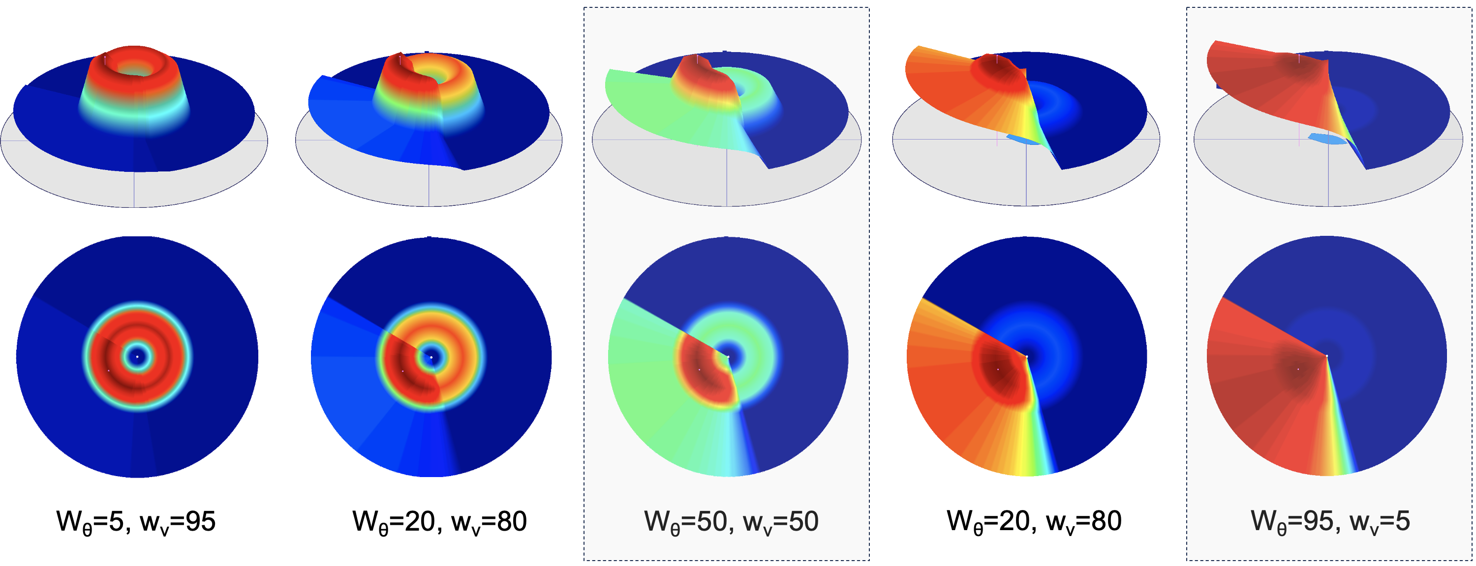
Figure 1.4: Five Couplings with Different weights: The heading-speed IvP function is created from a weighted combination of the individual heading and speed functions. Five examples are shown. In the left, the function primarily influences the desired speed, and on the right influences desired heading. In the middle, there is a balance on both heading and speed influence.
When the vehicle is not heading toward the save polygon, e.g., when it has first exited the save polygon, then the weights are 50-50. When the vehicle's current heading is on an intersection course with the save polygon, the weights are 95-5. These two cases are highlighted in Figure 1.4. The motivation for this is to have an IvP function that is more influential about ownship speed initially, to enhance safety when heading away from the save polygon. Once the vehicle is on a course to return to the save polygon, the influence on speed is reduced, while the influence on heading is retained.
An Example with IvP Function Output [top]
In the example below in Figure 1.5, the vehicle has just exited the save polygon. Prior to exiting the save polygon, the behavior produces no IvP function. On initial exit, the produced IvP function is structured to prefer headings that would result in a trajectory returning to the polygon. Once the vehicle has turned and its current heading is pointed toward the save polygon, the shape of the IvP function is based on coupling with a weighting like the example shown on the far right in Figures 1.4.
Figure 1.5: OpRegionV24 IvP Function in Save Mode: The vehicle has breached the save polygon and is producing an objective function to influence the vehicle to turn to the starboard to return to the save polygon.
1.5 Configuration Parameters and Examples [top]
The following configuration parameters are supported for the OpRegionV24 behaviors, in addition to the parameters support for all IvP behaviors.
Listing 1.1 - Configuration Parameters for the OpRegion Behavior.
| Parameter: | Description |
| breached_altitude_flag: | A MOOS variable-value pair to be posted when or if the vehicle breaches the altitude limit set by this behavior. Section 1.6. |
| breached_depth_flag: | A MOOS variable-value pair to be posted when or if the vehicle breaches the depth limit set by this behavior. Section 1.6. |
| breached_poly_flag: | A MOOS variable-value pair to be posted when or if the vehicle breaches the convex polygon op area limit set by this behavior. Section 1.6. |
| breached_time_flag: | A MOOS variable-value pair to be posted when or if the vehicle breaches the time limit set by this behavior. Section 1.6. |
| core_poly: | The nominal operation area, a convex polygon. Section 1.3.1. |
| draw_halt_status: | If true, a small (by default red) polygon is drawn around the vehicle when or if it exits the halt polygon, following the vehicle until it returns to the within the halt polygon. The default is true. Section 1.5.3. |
| draw_save_status: | If true, a small (by default yellow) polygon is drawn around the vehicle when or if it exits the save polygon, following the vehicle until it returns to the within the save polygon. The default is true. Section 1.5.3. |
| halt_poly: | A convex polygon area, outside of which the behavior will generation an all-stop indicator to the helm. Section 1.3.1. |
| max_time: | The max allowable time in seconds. |
| max_depth: | The max allowable depth in meters. |
| min_altitude: | The min allowable altitude in meters. |
| save_poly: | A convex polygon area, outside of which the behavior will generation an IvP function to return within the polygon. Section 1.3.1. |
| reset: | If set to true, and the behavior is currently in a mode where one of the operating envelopes (time, depth, altitude or position) has been breached, the behavior will be reset to original launch state. Section 1.3.4. |
| recover_spd: | The preferred speed for the vehicle when it is out of the save polygon, attempting to maneuver back in. The speed should be high enough to enable a turn, but likely slower than normal in case an exit is inevitable for other reasons. The default value is 0.8 meters per second. |
| trigger_entry_time: | The time required for the vehicle to have been within the halt polygon before triggering the halt polygon requirement. Section 1.3.2. |
| trigger_exit_time: | The time required to have been outside the polygon before declaring a polygon containment failure. Section 1.3.2. |
| trigger_on_poly_entry: | If true, the vehicle must first be in the halt polygon before the halt polygon constraint is enabled. The default is true. Section 1.3.2. |
| visual_hints: | Hints for visual properties in variables posted intended for rendering. See Section 1.5.3. |
Example Configuration (Minimal) [top]
Below is an minimal configuration block example, accepting default values for all other missing parameters:
Listing 1.2 - Example Minimal Config Block.
[[#lst_bhv_opregion_exam1]]
 Behavior = BHV_OpRegionV24
 {
   name = opr24
   pwt  = 300

   core_poly = pts={-80,-50:-30,-175:150,-100:95,25}
   save_dist = 5
   halt_dist = 15
 }
Example Configuration (Full) [top]
The below configuration shows all configuration parameters with defaults indicated where appropriate:
Listing 1.3 - Example Configuration Block.
[[#lst_bhv_opregion_exam]]
 Behavior = BHV_OpRegionV24
 {
   // General Behavior Parameters
   // ---------------------------
   name         = opr24               // example
   pwt          = 300                 // example
   updates      = OPREGION_UPDATES    // example

   // Params specific to this behavior
   // --------------------------------
                  max_time = 0         // default (seconds)
                 max_depth = 0         // default (meters)
              min_altitude = 0         // default (meters)
        trigger_entry_time = 1         // default (seconds)
         trigger_exit_time = 0.5       // default (seconds)

                 core_poly = pts={-80,-50:-30,-175:150,-100:95,25}
                 save_dist = 5
                 halt_dist = 15

    breached_altitude_flag = SAY_MOOS = min altitude has been exceeded
       breached_depth_flag = SAY_MOOS = max depth has been exceeded
        breached_poly_flag = SAY_MOOS = halt region has been violated
        breached_time_flag = SAY_MOOS = max mission time has been exceeded
                 save_flag = SAY_MOOS = save region has been violated
 [@               savex_flag = RECOVER_POSITION=$[OSX],$[OSY]
              visual_hints = vertex_size  = 0      // default
              visual_hints = edge_color   = aqua   // default
              visual_hints = edge_size    = 1      // default
 }
@]
Visual Configuration Options [top]
The visual artifacts generated by the OpRegionV24 behavior are related to the (a) the polygon regions and (b) small polygon indicators drawn around the vehicle to indicate state. The polygon regions are shown in Figure 1.1. The polygon indicators drawn around the vehicle are shown in Figure 1.2. The rendering style shown in these figures is the default, but the visual artifacts can be either turned off, or rendered in different colors or sizes.
There are five polygon renderings that can be modified: (1) the core polygon, (2) the save polygon, (3) the halt polygon, (4) the save status and (5) halt status polygons. There are also five visual aspects for each polygon that may be modified: (a) the vertex size, (b) the edge size, (c) the vertex color, (d) the edge color, (e) the label color.
By setting edge_color=green, this sets the default edge color for all five polygons. This can be overruled for say the core polygon by setting core_edge_color=white. If the latter is left unspecified, the default aspects are used. In the example lines below, the first five lines are the default aspects for all polygons. The vertex color is moot since the vertex size is zero. The middle three lines overrule the default edge colors for the three region polygons with the colors shown in Figure 1.1. The last two lines below override the edge colors for the save and halt status polygons to yellow and red as shown in Figure 1.2. All lines below represent the defaults used by the OpRegionV24 behavior if no visual hints were provided in the behavior configuration.
   visual_hints = vertex_size = 0
   visual_hints = edge_size = 1
   visual_hints = vertex_color = gray50
   visual_hints = edge_color = gray50
   visual_hints = label_color = off

   visual_hints = core_edge_color = gray30
   visual_hints = save_edge_color = gray50
   visual_hints = halt_edge_color = pink

   visual_hints = save_status_edge_color = yellow
   visual_hints = halt_status_edge_color = red
The posting of the save status and halt status polygons (Figure 1.2) can be disabled simply with:
   draw_save_status = false
   draw_halt_status = false
1.6 Flags and Macros [top]
The OpRegionV24 behavior supports the below set of event flags in addition to the standard behavior flags, e.g., endflags, runflags. These are:
- breached_altitude_flag: If the minimum altitude constraint is enabled, this flag or flags are posted once, when or if the vehicle altitude first becomes lower than the limit.
- breached_depth_flag: If the maximum depth constraint is enabled, this flag or flags are posted once, when or if the vehicle depth first becomes greater than the limit.
- breached_poly_flag: If the halt polygon is specified, this flag or flags are posted once, when or if the vehicle exits the polygon, and has been outside the polygon for the duration specified by the trigger_exit_time.
- breached_time_flag: If the maximum time constraint is enabled, this flag or flags are posted once, when or if the vehicle first exits the maximum time limit.
- save_flag: If the save polygon is enabled, this flag is posted once, when or if the vehicle first exits the save polygon.
- savex_flag: If the save polygon is enabled, this flag is posted when or if the vehicle first exits the save polygon, and on each iteration thereafter so long as the vehicle remains outside the save polygon.
The following macros are supported in the OpRegionV24 behavior. These macros will be expanded in any event flag, including event flags defined for all IvP behaviors as well as event flags defined only for the OpRegionV24 behavior.
- CORE_POLY: The specification of the polygon representing the core operation area.
- SAVE_POLY: The specification of the polygon representing the operation area, outside which the vehicle will actively attempt to return to.
- HALT_POLY: The specification of the polygon representing the halt area, outside which the vehicle will post an emergency all-stop message.
- ALT_LEFT: If a minimum altitude is enabled, this is the number of meters remaining before the minimum altitude has been breached.
- DEPTH_LEFT: If a maximum depth is enabled, this is the number of meters remaining before the maximum depth has been breached.
- TIME_LEFT: If a maximum mission time is enabled, this is the number of seconds remaining before the maximum mission time has been breached.
- SECS_IN_HALT_POLY: The number of seconds the vehicle has been inside the halt polygon.
- SECS_OUT_HALT_POLY: The number of seconds the vehicle has been outside the halt polygon (once it has been inside).
- SECS_OUT_SAVE_POLY: The number of seconds the vehicle has been outside the save polygon (once it has been inside).
- DIST_TO_CORE: Distance in meters of the vehicle to the boundary of the core polygon.
- TRAJ_DIST_TO_CORE: Distance in meters of the vehicle to the boundary of the core polygon, in the direction of the current vehicle trajectory.
- ETA_TO_CORE: Estimated time of arrival (ETA), in seconds, of the vehicle if it were to instantaneously change direction and drive directly to the closest point of exit of the core polygon at the top vehicle speed.
- TRAJ_ETA_TO_CORE: ETA of the vehicle on its current heading and speed reaching the boundary of the core polygon.
- DIST_TO_SAVE: Distance in meters of the vehicle to the boundary of the save polygon.
- TRAJ_DIST_TO_SAVE: Distance in meters of the vehicle to the boundary of the save polygon, in the direction of the current vehicle trajectory.
- ETA_TO_SAVE: Estimated time of arrival (ETA), in seconds, of the vehicle if it were to instantaneously change direction and drive directly to the closest point of exit of the save polygon at the top vehicle speed.
- TRAJ_ETA_TO_SAVE: ETA of the vehicle on its current heading and speed reaching the boundary of the core polygon.
- DIST_TO_HALT: Distance in meters of the vehicle to the boundary of the halt polygon.
- TRAJ_DIST_TO_HALT: Distance in meters of the vehicle to the boundary of the halt polygon, in the direction of the current vehicle trajectory.
- ETA_TO_HALT: Estimated time of arrival (ETA), in seconds, of the vehicle if it were to instantaneously change direction and drive directly to the closest point of exit of the halt polygon at the top vehicle speed.
- TRAJ_ETA_TO_HALT: ETA of the vehicle on its current heading and speed reaching the boundary of the halt polygon.
Document Maintained by: mikerb@mit.edu
Page built from LaTeX source using texwiki, developed at MIT. Errata to issues@moos-ivp.org. Get PDF