IvP Helm | Utils | Labs | Help

pShare
pLogger
pAntler
iRemote
pMarineViewer
uHelmScope
Geometry Utilities
uTimerScript
pBasicContactMgr
pContactMgrV20
uProcessWatch
uLoadWatch
pNodeReporter
uXMS
uSimMarineV22
uSimMarine
pHostInfo
uPokeDB
uQueryDB
pEchoVar
pObstacleMgr
pDeadManPost
iSay
pRealm
pSearchGrid
uTermCommand
uSimCurrent
The alogview Utility
Alog Command Line Utils
uMAC Utilities
Enabling Appcasting
On Demand Appcasting
uFldNodeBroker
uFldShoreBroker
uFldNodeComms
uFldMessageHandler
uFldHazardSensor
uFldHazardMgr
uFldHazardMetric
uFldBeaconRangeSensor
uFldContactRangeSensor
uFldCollisionDetect
uFldCollObDetect
uFldObstacleSim
uFldScope
uFldPathCheck
Appendix Colors
Appendix Logic
uFldContactRangeSensor: Detecting Contact Ranges
Maintained by: mikerb@mit.edu  Get PDF
1 Overview
2 Using uFldContactRangeSensor
2.1 Typical Topology
2.2 Required MOOS Variable Bridges
2.3 Range Requests and Range Reports
2.4 Configuring the Range Criteria
2.5 Adding Exponentially Decaying Detection Probability Beyond Range
2.6 Limiting the Arcs of Vehicle Range Requests
2.7 Limiting the Frequency of Vehicle Range Requests
2.8 Producing Range Measurements with Noise
3 Configuration Parameters of uFldContactRangeSensor
4 Publications and Subscriptions for uFldContactRangeSensor
4.1 Variables Published by uFldContactRangeSensor
4.2 Variables Subscribed for by uFldContactRangeSensor
5 Terminal and AppCast Output
6 Interaction between uFldContactRangeSensor and pMarineViewer
7 The Hugo Example Mission Using uFldContactRangeSensor
1 Overview
The uFldContactRangeSensor application is a tool for simulating range measurements to off-board contacts, as a proxy for an on-board active sonar sensor. The range-only measurements are provided conditionally, depending on the range between the pinging vehicle and the contact. The simulator may optionally be configured to provide range measurements with noise.
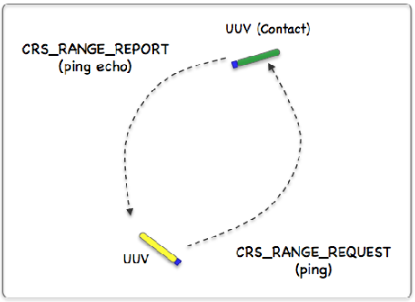
Figure 1.1: Simulated Active Sonar: A vehicle determines its range to another vehicle by producing a simulated sonar ping (a range request to the simulator), and the simulator conditionally responds to the querying vehicle with a report containing the range to nearby vehicles. All vehicles send frequent and regular node reports to the simulator so the simulator can report the range between any two vehicles at any time. The simulator may or may not reply to the range request depending on the range between the two vehicles and thresholds configured by the user.
In the uFldContactRangeSensor application, the beacon and vehicle locations are known to the simulator, and a tidy RANGE_REPORT message is sent to the vehicle(s) as a proxy to the actual range sensor and calculations that would otherwise reside on the vehicle. The MOOS app may be configured to have beacons provide a range report either (a) solicited with a range request, or (b) unsolicited. One may also configure the range at which a range request will be heard, and the range at which a range report will be heard. The app may be further configured to either (1) include the beacon location and ID, or (2) not include the beacon location or ID.
2 Using uFldContactRangeSensor
2.1 Typical Topology [top]
The typical module topology is shown in Figure 2.1 below. Multiple vehicles may be deployed in the field, each periodically communicating with a shoreside MOOS community running a single instance of uFldContactRangeSensor. Each vehicle regularly sends a node report noted by the simulator to keep an updated calculation of each vehicle to each simulated beacon. When a vehicle wants to simulate a ping, or range request, it generates the CRS_RANGE_REQUEST message sent to the shore. After the simulator calculates the range, a reply message, CRS_RANGE_REPORT message is sent to the vehicle, using pShare or similar app.
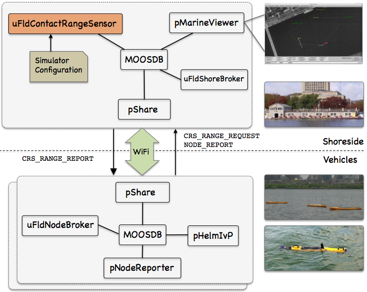
Figure 2.1: Typical uFldContactRangeSensor Topology: The simulator runs in a shoreside computer MOOS community. All deployed vehicles periodically send node reports to the shoreside community. The simulator maintains a running estimate of the range between vehicles, modulo latency. A vehicle simulates a ping by sending a range request to shore and receiving a range report in return from the simulator. The simulator also posts visual artifacts (VIEW_RANGE_PULSE messages) read by the pMarineViewer app optionally running shoreside.
If running a pure simulation (no physically deployed vehicles), both MOOS communities may simply be running on the same machine configured with distinct ports. The pShare application is shown here for communication between MOOS communities, but there are other alternatives for inter-community communication and the operation of uFldContactRangeSensor is not dependent on the manner of inter-communication communications.
2.2 Required MOOS Variable Bridges [top]
Using uFldContactRangeSensor requires certain information flowing between the shoreside and vehicles communities as shown in Figure 2.1. From the vehicle to the shoreside, three variables need to be bridged. The below three lines should appear in the uFldNodeBroker configuration block on all vehicles.
   // Bridges from Vehicle to Shoreside - in uFldNodeBroker configuration

   bridge =  src=APPCAST
   bridge =  src=NODE_REPORT_LOCAL,  alias=NODE_REPORT
   bridge =  src=CRS_RANGE_REQUEST
The first two lines above would likely already be present due to their use in other applications. The CRS_RANGE_REQUEST is generated locally on the vehicle and sent to the shoreside community running uFldContactRangeSensor. The above three lines may also be found in the Hugo example mission discussed in Section 7.
The below two lines should appear in the uFldShoreBroker configuration block in the shoreside MOOS community.
   // Bridges from Shoreside to Vehicle - in uFldShore Broker configuration

   bridge =  src=APPCAST_REQ
   bridge =  src=CRS_RANGE_REPORT_$V, alias=CRS_RANGE_REPORT
The first line deals with appcasting and would likely be present anyway due to its use in other applications as well. The second line ensures that a separate bridge is made for all distinct known vehicles, as they become known to the shoreside. A range report posted by uFldContactRangeSensor to be sent to archie would be posted locally in the shoreside to the variable CRS_RANGE_REPORT_ARCHIE which would be sent only to the archie vehicle by pShare.
2.3 Range Requests and Range Reports [top]
Range requests are made from vehicles to the simulator of the form:
CRS_RANGE_REQUEST = "name=archie"
The simulator only needs to know the requesting vehicle's name. It is also aware of the requesting and other vehicles' locations via incoming NODE_REPORT messages. When a range request is made, the simulator applies range and other criteria, discussed in the following sections. For a request from a vehicle named archie for example, the simulator may reply with a range report similar to:
CRS_RANGE_REPORT_ARCHIE = "range=126.54,target=jackal,time=19656022406.44"
If the ground_truth is set to true (the default), ground truth reports are also published of the form:
CRS_RANGE_REPORT_GT_ARCHIE = "range=127.12,target=jackal,time=19656022406.44"
These reports have the simulated range noise removed and are not typically sent to the vehicles. If the simulator is configured with report_vars set to "short", the above to posts are made with the following form instead:
    CRS_RANGE_REPORT_   = "vname=archie,range=126.54,target=jackal,time=19656022406.44"
    CRS_RANGE_REPORT_GT = "vname=archie,range=127.12,target=jackal,time=19656022406.44"
The name of the requesting vehicle is embedded in the report content rather than the MOOS variable. The default setting for report_vars is "long", producing the first style of reports above.
2.4 Configuring the Range Criteria [top]
When a ping is received by the simulator, via CRS_RANGE_REQUEST, the simulator may or may not reply with an range report depending on the range between the two vehicles. The uFldContactRangeSensor simulator has two range configuration parameters:
    reach_distance = default = <meters>    // or "nolimit"
    reply_distance = default = <meters>    // or "nolimit"
Two separate range parameters are used so that the simulator can support scenarios where some vehicles have a more powerful sonar than others, and some targets are harder to detect (absorb or deflect more energy) than others. Both parameters are given in meters. If the user provides no configuration parameters, all vehicles will default to have the same reach and reply distances of 100 meters. The default values may be overridden with something like:
    reach_distance = default = 120
    reply_distance = default = 80
The above two lines, in effect, are the same as reach_distance = 100 and reply_distance = 100. Things become interesting when individual vehicles are given values different from the default. Consider the more advantageously configured vehicle, victor, below:
    reach_distance = victor = 250
    reply_distance = victor = 20
If either the reach or reply distance for a given pair of vehicles is set to nolimit, then a range report will always be generated regardless of current range between the two vehicles. Future enhancements to this simulator module may include the factoring of vehicle speed and relative bearing to one another in the threshold determination of sending range reports.
2.5 Adding Exponentially Decaying Detection Probability Beyond Range [top]
If one desires an additional probability to as to whether or not the pinging vehicle receives a ping from the pinged vehicle beyond the reach_distance + reply_distance specified in the MOOS configuration file. This is normally off unless configured in the application's configuration file. In order to use this feature, the following configuration parameter must be set:
exponential_decay = true = // default is "false"
When the exponential_decay configuration parameter is turned on, and the vehicle requesting the range report is within the reach_distance + reply_distance range of the requested vehicle, this configuration will have no effect. However, if the vehicles are beyond this range, this assign a probability, which decays exponentially with increasing range a probability that a range report will still be received. The actual probability is calculated by the following equation:

where Probability is the probability that a range report will be received, Max is the reach_distance + reply_distance, and Range is the Range between the two vehicles. Figure~ 2.2 is a graphical representation of the probability of detection as a function of range when this configuration is turned on.
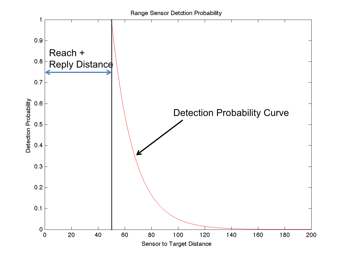
Figure 2.2: Exponential Decay Configuration: If the exponential_decay configuration parameter is set to true, the requesting vehicle will have an additional probability of detecting the requested vehicle even when beyond the reach_distance + reply_distance range, which is set to 50 in this example.
2.6 Limiting the Arcs of Vehicle Range Requests [top]
This feature allows a vehicle to limit the range sensing capability to use specified arcs with respect to the relative heading of the vehicle. For instance a user could limit the sensor to only detect vehicles that are within 45 degrees of directly ahead, or 315 degrees relative to 45 degrees relative.
Multiple sensor arcs can be specified, in one degree increments. The default is 360 degree coverage. To specify a range arc, two numbers must be specified, separated by a colon. The first number specifies the left side of the arc, and the second represents the right side of the arc. Valid values for relative headings are between 0 and 359 degrees. Multiple arcs can be separated by commas, or by multiple lines. Figure~ 2.3 shows some example arcs of where requesting vehicles can detect requested vehicles. Some example are configurations are as follows:
    sensor_arc = 360 // default, 360 degree coverage
    sensor_arc = 315:45  // 90 degree coverage for front.
    sensor_arc = 45:135,225:315 // two 90 degree arcs centered broadside
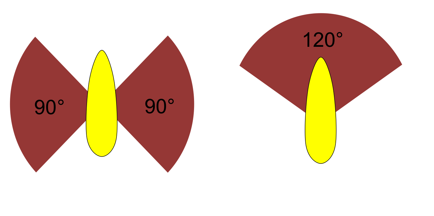
Figure 2.3: Example Sensor Arc Configurations: Two possible range sensor arc configurations.
2.7 Limiting the Frequency of Vehicle Range Requests [top]
From the perspective of operating a vehicle, one may ask: why not request a range report (ping) as often as possible? There may be reasons why this is not feasible outside simulation. Limits may exist due to power budgets of the vehicle, and there may be prevailing protocols that make it at least impolite to be frequently pinging.
To reflect this limitation, the uFldContactRangeSensor utility may be configured to limit the frequency in which a vehicle's range request (or ping) will be honored with a range report reply. By default this frequency is set to once every 30 seconds for all vehicles. The default for all vehicles may be changed with the following configuration in the .moos file:
ping_wait = default = 60
The limits for a particular vehicle may be set with a similar configuration line:
ping_wait = henry = 90
2.8 Producing Range Measurements with Noise [top]
In the default configuration of uFldContactRangeSensor, range reports are generated with the most precise range estimate as possible, with the only error being due to the latency of the communications generating the range request and range report. Additional noise/error may be added in the simulator for each range report with the following configuration parameter:
rn_algorithm = uniform,pct=0.12 // Values in the range [0,1]
or
rn_algorithm = gaussian,sigma=20 // Values in the range [0,inf]
For uniform random noise, the noise level, θ, set with the parameter pct subfield, will generate a noisy range from an otherwise exact range measurement r, by choosing a value in the range [{θ}{r}, r + {θ}{r} ]. The range without noise, i.e., the ground truth, may also be reported by the simulator if desired by setting the configuration parameter:
ground_truth = true
This will result in an additional MOOS variables posted, CRS_RANGE_REPORT_GT, with the same format as CRS_RANGE_REPORT, except the reported range will be given without noise.
3 Configuration Parameters of uFldContactRangeSensor
The following parameters are defined for uFldContactRangeSensor. A more detailed description is provided in other parts of this section. Parameters having default values are indicated so.
Listing 3.1: Configuration Parameters for uFldContactRangeSensor.
| allow_echo_types: | A list of platform types for which an reply will be generated from another source. Legal values: auv, uuv, usv, asv, kayak, kingfisher, glider, and ship. The default is the empty set, indicating that all types are honored. |
| ground_true: | If true, ground truth reports are also published alongside the normal range reports, with noise removed. This information is not bridge to the vehicles however. Legal values: true, false. The default is true. Section 2.3. |
| ignore_group: | If specified, incoming node reports that match this group will be ignored. Introduced after Release 19.8.x. |
| ping_color: | Visual preference: color of initiating ping message. Legal values: any color in the Colore Appendix. The default is white. |
| ping_wait: | Minimum seconds enforced between pings. The default is 30. Section 2.7. |
| reach_distance: | Distance out to which the pinging vehicle will be heard. Legal values: any numerical value or the keyword "nolimit". The default is 100. Section 2.4. |
| reply_distance: | Distance out to which the pinged vehicle will be heard. Legal values: any numerical value or the keyword "nolimit". The default is 100. Section 2.4. |
| exponential_decay: | Determines if the there is an exponentially decaying with range probability of detection beyond the reach_distance + reply_distance. Default is false. Section 2.5. |
| reply_color: | Visual preference: color of replying message Legal values: any color in Color Appendix. The default is chartreuse. |
| report_vars: | Determines if CRS_RANGE_REPORT or CRS_RANGE_REPORT_VNAME, or both are published for individual range reports. Legal settings are short, long, or both. The default is short. |
| sensor_arcs: | Set arcs relative to the heading of the vehicle in which the range sensor is able to detect vehicles. The default is 360 degrees. Section 2.6. |
| rn_algorithm: | Algorithm for adding random noise to the range measurement. Legal parameter values discussed in Section 2.8. The default is no noise. |
| report_vars: | Determines variable name style used for range reports. Legal values: short, long, both. The default is long. Section 2.3. |
An Example MOOS Configuration Block [top]
To see an example MOOS configuration block, enter the following from the command line:
$ uFldContactRangeSensor --example or -e
This will show the output shown in Listing 3.2 below.
Listing 3.2 - Example configuration of the uFldContactRangeSensor application.
    1  ===============================================================
    2  uFldContactRangeSensor Example MOOS Configuration
    3  ===============================================================
    4
    5  ProcessConfig = uFldContactRangeSensor
    6  {
    7    AppTick   = 4
    8    CommsTick = 4
    9
   10    // Configuring aspects of the vehicles in the sim
   11    reach_distance = default = 100  // in meters or {nolimit}
   12    reply_distance = default = 100  // in meters or {nolimit}
   13    ping_wait      = default = 30   // in seconds
   14
   15    push_distance  = jackal  = 50
   16    push_distance  = archie  = 190
   17    ping_wait      = archie  = 32
   18
   19    // Configuring manner of reporting
   20    report_vars    = short // or {long, both}
   21    ground_truth   = true  // or {false}
   22
   23    // Configuring visual artifacts
   24    ping_color     = white
   25    reply_color    = chartreuse
   26
   27    // Configuring Artificial Noise
   28    rn_algorithm   = uniform,pct=0.04
   29
   31    // Configuring Probability Detection with Exponential Decay
   32    exponential_decay = false   // default is false
   33
   34    // Configuring Sensor Arcs
   35    sensor_arc = 45:135,225:315 // for two side arcs
   36    // sensor_arc = 315:45      // just for front
   37    // sensor_arc = 360         // default, sets full circle
   38  }
4 Publications and Subscriptions for uFldContactRangeSensor
The interface for uFldContactRangeSensor, in terms of publications and subscriptions, is described below. This same information may also be obtained from the terminal with:
$ uFldContactRangeSensor --interface or -i
4.1 Variables Published by uFldContactRangeSensor [top]
The primary output of uFldContactRangeSensor to the MOOSDB is the posting of range reports and visual cues for the range reports.
- APPCAST: Contains an appcast report identical to the terminal output. Appcasts are posted only after an appcast request is received from an appcast viewing utility. Section 5.
- CRS_RANGE_REPORT: A report on the range from a particular vehicle to the pinging vehicle. Section 2.4.
- CRS_RANGE_REPORT_NAMEJ: A report on the range from a particular named NAMEJ, to the pinging vehicle.
- VIEW_RANGE_PULSE: A description for visualizing the beacon range report. Section 6.
4.2 Variables Subscribed for by uFldContactRangeSensor [top]
The uFldContactRangeSensor application will subscribe for the following MOOS variables:
- APPCAST_REQ: A request to generate and post a new apppcast report, with reporting criteria, and expiration.
- CRS_RANGE_REQUEST: A request to generate range reports for all targets to all vehicles within range of the target.
- NODE_REPORT: A report on a vehicle location and status.
- NODE_REPORT_LOCAL: A report on a vehicle location and status.
Command Line Usage of uFldContactRangeSensor [top]
The uFldContactRangeSensor application is typically launched as a part of a batch of processes by pAntler, but may also be launched from the command line by the user. To see command-line options enter the following from the command-line:
$ uFldContactRangeSensor --help or -h
This will show the output shown in Listing 1 below.
Listing 1 - Command line usage for the uFldContactRangeSensor tool.
   1  Usage: uFldContactRangeSensor file.moos [OPTIONS]
   2
   3  Options:
   4    --alias=<ProcessName>
   5        Launch uFldContactRangeSensor with the given process
   6        name rather than uFldContactRangeSensor.
   7    --example, -e
   8        Display example MOOS configuration block
   9    --help, -h
  10        Display this help message.
  11    --version,-v
  12        Display the release version of uFldContactRangeSensor.
5 Terminal and AppCast Output
The uFldContactRangeSensor application produces some useful information to the terminal and identical content through appcasting. An example is shown in Listing 1 below. On line 2, the name of the local community or vehicle name is listed on the left. On the right, "0/0(848) indicates there are no configuration or run warnings, and the current iteration of uFldContactRangeSensor is 848. Lines 4-10 convey the prevailing configuration settings. They may reflect the default values or values read from the configuration block like the one shown previously in Listing 3.2.
Listing 1 - Example uFldContactRangeSensor console or appcast output.
    1  ===================================================================
    2  uFldContactRangeSensor shoreside                           0/0(848)
    3  ===================================================================
    4  Default Ping Wait:        30
    5  Random Noise Algorithm:   uniform
    6  Random Noise Uniform Pct: 0.04
    7  Gaussian Noise:           0
    8  Ping Color:               white
    9  Echo Color:               chartreuse
   10  Ground Truth Reporting:   true
   11  Allow Echo Types:         all types
   12
   13  Vehicles(3):
   14          Node  Ping  Push  Pull  Pings  Echos  Too   Too  Echos
   15  VName   Reps  Wait  Dist  Dist  Gen'd  Rec'd  Freq  Far  Sent
   16  ------  ----  ----  ----  ----  -----  -----  ----  ---  -----
   17  archie  411   32    190   100   11     5      6     0    0
   18  betty   410   30    100   100   0      0      0     0    0
   19  jackal  411   30    50    100   0      0      0     0    5
   20
   21  ===================================================================
   22  Most Recent Events (8):
   23  ===================================================================
   24  [211.60]: ARCHIE  <--   JACKAL
   25  [211.60]: ARCHIE  ----))
   26  [181.40]: ARCHIE  ----))  XXX too frequent. (4.03)
   27  [177.37]: ARCHIE  <--   JACKAL
   28  [177.37]: ARCHIE  ----))
   29  [146.23]: ARCHIE  ----))  XXX too frequent. (30.66)
   30  [144.22]: ARCHIE  ----))  XXX too frequent. (28.64)
   31  [115.58]: ARCHIE  <--   JACKAL
In the block of output beginning on line 13, the information is organized by vehicle name in each row. The first two columns show the vehicle name and number of node reports received for that vehicles.
The next three columns reflect configuration settings for particular vehicles. For example, the Ping Wait time of 32 seconds reflects line 17 in Listing 3.2. The Push Dist value reflects line 16 in Listing 3.2. The last five columns reflect the results of pings generated by vehicles. THe Pings Gen'd column shows how many CRS_SENSOR_REQUEST messages have been received by that vehicle. The next column shows how many replies were sent back to the vehicle. The Too Freq and Too Far columns explain why a ping may not have been replied. The Echos Sent column shows how many echos were sent to others about that vehicle. In this snapshot, archie has receieved five ping echos about the jackal vehicle.
The last block, lines 21-31 show the most recent events with their timestamps. Line 28 shows an example where a ping was generated by archie, followed by a reply about jackal on line 27. Lines like 26 indicate that a ping was rejected by the simulator as being too soon after the previous ping.
6 Interaction between uFldContactRangeSensor and pMarineViewer
The uFldContactRangeSensor application will post certain messages to the MOOSDB that may be subscribed for by GUI based applications like pMarineViewer for visualizing the posting of CRS_RANGE_REPORT and CRS_RANGE_REQUEST messages. A range pulse message conveys visually the generation of a range report, or the receipt of a range request. The pulse is rendered as a ring with a growing radius having the vehicle at the center. Range pulses are posted to the MOOS variable VIEW_RANGE_PULSE with a form similar to:
    VIEW_RANGE_PULSE = "x=-40,y=-150,radius=40,duration=15,fill=0.25,fill_color=green,
                       label=04,edge_color=green,time=3892830128.5,edge_size=1"
The x and y parameters convey the center of the pulse. The radius parameter indicates the radius of the circle at its maximum. The duration parameter is the number of seconds the pulse will be rendered. The pulse will grow its radius linearly from zero meters at zero seconds to radius meters at duration seconds. The fill parameter is in the range [0,1], where 0 is full transparency (clear) and 1 is fully opaque. The pulse transparency increases linearly as the range ring is rendered. The starting transparency at radius=0 is given by the fill parameter. The transparency at the maximum radius is zero. The fill_color parameter specifies the color rendered to the internal part of the range pulse. The choice of legal colors is described in the Color Appendix. The label is a string that uniquely identifies the range instance to consumers like pMarineViewer. As with other objects in pMarineViewer, if it receives an object the same label and type as one previously received, it will replace the old object with the new one in its memory. The edge_color parameter describes the color of the ring rendered in the range pulse. The edge_size likewise describes the line width of the rendered ring. The time parameter indicates the UTC time at which the range pulse object was generated.
One further note to developers of other apps perhaps wishing to also generate a range pulse for viewing - the recommended manner to generate a range pulse string is to create an instance of the XYRangePulse class using the defined class interface. The string should be obtained by invoking the serialization method for that class. This will better ensure compatibility as the software evolves. The class is defined in lib_geometry in the MOOS-IvP tree.
7 The Hugo Example Mission Using uFldContactRangeSensor
The hugo mission is distributed with the MOOS-IvP source code and contains a ready example of the uFldContactRangeSensor application. Assuming the reader has downloaded the source code available at www.moos-ivp.org and built the code according to the documentation, the hugo mission may be launched by:
    $ cd moos-ivp/ivp/missions/m8_hugo/
    $ ./launch.sh 10
The argument, 10, in the line above will launch the simulation in 10x real time. Once this launches, the pMarineViewer GUI application should launch and the mission may be initiated by hitting the DEPLOY button. Two vehicles should be visibly moving, one surface vehicle labeled "archie" and one UUV labeled "jackal", as shown in Figure 7.1.
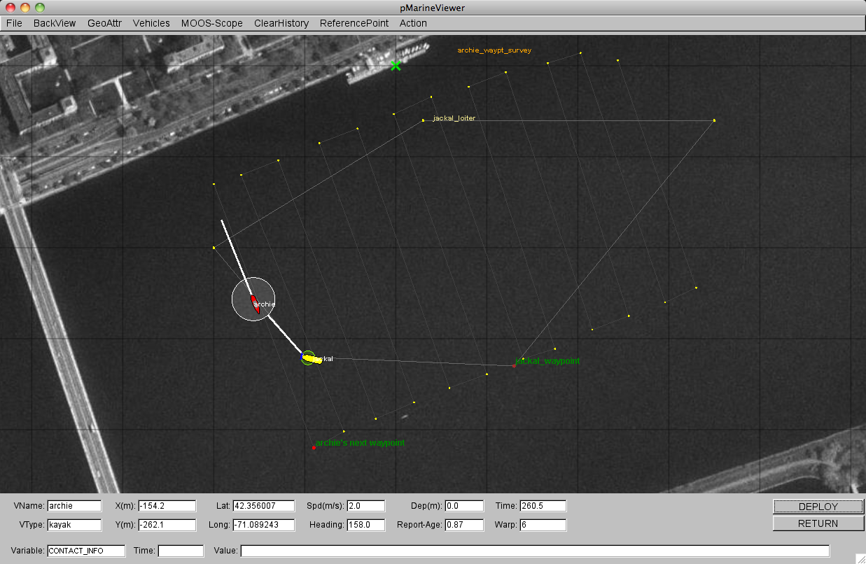
Figure 7.1: The Hugo Example Mission: The Hugo example mission involves two simulated vehicles. The first vehicle is a surface vehicle, archie, traversing a lawnmower shaped search pattern. The second vehicle, is a UUV, jackal, traversing a polygon pattern overlapping the first pattern. Periodically archie emits a ping (range request). This example contains three distinct MOOS communities - one for each simulated vehicle, and one for the shoreside community running uFldContactRangeSensor.
The surface vehicle will traverse a survey pattern over the region shown in Figure 7.1, periodically generating a range request (ping). With each range request, a white range pulse should be visible around the vehicle. Almost immediately afterwards, a range report for each neighboring vehicle within range is generated and a green range pulse around each ``target'' vehicle is rendered. The snapshot in Figure 7.1 depicts a moment in time where the range request visual pulses are around both vehicles. The larger pulse around the surface vehicle indicates it was generated just prior to the reply pulse around the UUV.
How does the simulated vehicle generate a range request? In practice a user may implement an intelligent module to reason about when to generate requests, but in this case the uTimerScript application is used by creating a script that repeats endlessly, generating a range request once every 25-35 seconds. The script is also conditioned on (NAV_SPEED > 0), so the pinging doesn't start until the vehicle is deployed. The configuration for the script can be seen in the uTimerScript configuration block in the shoreside.moos file. More on the uTimerScript application can be found in
http://oceanai.mit.edu/ivpman/apps/uTimerScript
Page built from LaTeX source using texwiki, developed at MIT. Errata to issues@moos-ivp.org. Get PDF