IvP Helm | Utils | Labs | Help

pShare
pLogger
pAntler
iRemote
pMarineViewer
uHelmScope
Geometry Utilities
uTimerScript
pBasicContactMgr
pContactMgrV20
uProcessWatch
uLoadWatch
pNodeReporter
uXMS
uSimMarine
uSimMarineV22
pHostInfo
uPokeDB
uQueryDB
pEchoVar
pObstacleMgr
pDeadManPost
iSay
pRealm
pSearchGrid
uTermCommand
uSimCurrent
The alogview Utility
Alog Command Line Utils
uMAC Utilities
Enabling Appcasting
On Demand Appcasting
uFldNodeBroker
uFldShoreBroker
uFldNodeComms
uFldMessageHandler
uFldHazardSensor
uFldHazardMgr
uFldHazardMetric
uFldBeaconRangeSensor
uFldContactRangeSensor
uFldCollisionDetect
uFldCollObDetect
uFldObstacleSim
uFldScope
uFldPathCheck
Appendix Colors
Appendix Logic
uSimMarine: Basic Vehicle Simulation
Maintained by: mikerb@mit.edu  Get PDF
src: project-pavlab/appdocs/app_usimmarine
1 Overview
2 Configuration Parameters for uSimMarine
3 Publications and Subscriptions for uSimMarine
3.1 Variables Published by uSimMarine
3.2 Variables Subscribed for by uSimMarine
3.3 Command Line Usage of uSimMarine
4 Setting the Initial Vehicle Position, Pose and Trajectory
5 Propagating the Vehicle Speed, Heading, Position and Depth
5.1 Propagating the Vehicle Speed
5.2 Propagating the Vehicle Heading
5.3 Propagating the Vehicle Position
5.4 Propagating the Vehicle Depth
6 Propagating the Vehicle Altitude
7 Simulation of External Drift
7.1 External X-Y Drift from Initial Simulator Configuration
7.2 External X-Y Drift Received from Other MOOS Applications
8 The ThrustMap Data Structure
8.1 Automatic Pruning of Invalid Configuration Pairs
8.2 Automatic Inclusion of Implied Configuration Pairs
8.3 A Shortcut for Specifying the Negative Thrust Mapping
8.4 The Inverse Mapping - From Speed To Thrust
8.5 Default Behavior of an Empty or Unspecified ThrustMap
1 Overview
The uSimMarine application is a simple 3D vehicle simulator that updates vehicle state, position and trajectory, based on the present actuator values and prior vehicle state. The typical usage scenario has a single instance of uSimMarine associated with each simulated vehicle, as shown in Figure 1.1.
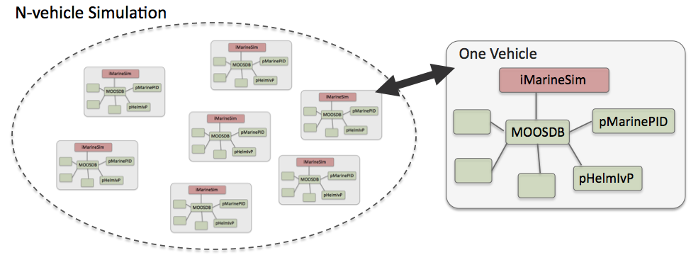
Figure 1.1: Typical uSimMarine Usage: In an N-vehicle simulation, an instance if uSimMarine is used for each vehicle. Each simulated vehicle typically has its own dedicated MOOS community. The IvP Helm (pHelmIvP) publishes high-level control decisions. The PID controller (pMarinePID) converts the high-level control decisions to low-level actuator decisions. Finally the simulator (uSimMarine) reads the low-level actuator postings to produce a new vehicle position.
This style of simulation can be contrasted with simulators that simulate a comprehensive set of aspects of the simulation, including multiple vehicles, and aspects of the environment and communications. The uSimMarine simulator simply focuses on a single vehicle. It subscribes for the vehicle navigation state variables:
- NAV_X, NAV_Y, NAV_SPEED, NAV_HEADING, and NAV_DEPTH
as well as the actuator values
- DESIRED_RUDDER, DESIRED_THRUST, and DESIRED_ELEVATOR.
The simulator accommodates a notion of external drifts applied to the vehicle to crudely simulate current or wind. These drifts may be set statically or may be changing dynamically by other MOOS processes. The simulator also may be configured with a simple geo-referenced data structure representing a field of water currents.
Under typical UUV payload autonomy operation, the simulator and pMarinePID MOOS modules would not be present. The vehicle's native controller would handle the role of pMarinePID, and the vehicle's native navigation system (and the vehicle itself) would handle the role of the simulator.
2 Configuration Parameters for uSimMarine
The following parameters are defined for uSimMarine. A more detailed description is provided in other parts of this section. Parameters having default values are indicated so in parentheses below.
Listing 2.1 - Configuration Parameters for uSimMarine.
| buoyancy_rate: | Rate, in meters per second, at which vehicle floats to surface at zero speed. The default is zero. Section 5.4. |
| current_field: | A file containing the specification of a current field. |
| current_field_active: | If true, simulator uses the current field if specified. |
| default_water_depth: | Default value for local water depth for calculating altitude (0). |
| drift_vector: | A pair of external drift values, direction and magnitude. |
| rotate_speed: | An external rotational speed in degrees per second (0). |
| drift_x: | An external drift value applied in the x direction (0). |
| drift_y: | An external drift value applied in the y direction (0). |
| max_acceleration: | Maximum rate of vehicle acceleration in  (0.5). (0.5). |
| max_deceleration: | Maximum rate of vehicle deceleration in  (0.5). (0.5). |
| max_depth_rate: | Maximum rate of vehicle depth change, meters per second. The defauls is 0.5. Section 5.4. |
| max_depth_rate_speed: | Vehicle speed at which max depth rate is achievable (2.5). Section 5.4. |
| prefix: | Prefix of MOOS variables published. The default is USM_. |
| sim_pause: | If true, the simulation is paused. The default is false. |
| start_depth: | Initial vehicle depth in meters. The default is zero. Section 4. |
| start_heading: | Initial vehicle heading in degrees. The default is zero. Section 4. |
| start_pos: | A full starting position and trajectory specification. Section 4. |
| start_speed: | Initial vehicle speed in meters per second. The default is zero. Section 4. |
| start_x: | Initial vehicle x position in local coordinates. The default is zero. Section 4. |
| start_y: | Initial vehicle y position in local coordinates. The default is zero. Section 4. |
| thrust_factor: | A scalar correlation between thrust and speed. The default is 20. |
| thrust_map: | A mapping between thrust and speed values. Section 8. |
| thrust_reflect: | If true, negative thrust is simply opposite positive thrust. The default is false. Section 8. |
| turn_loss: | A range [0, 1] affecting speed lost during a turn. The default is 0.85. |
| turn_rate: | A range [0, 100] affecting vehicle turn radius, e.g., 0 is an infinite turn radius. The default is 70. |
An Example MOOS Configuration Block [top]
An example MOOS configuration block is provided in Listing 2.2 below. This can also be obtained from a terminal window with:
$ uSimMarine --example or -e
Listing 2.2 - Example configuration of the uSimMarine application.
    1  ===============================================================
    2  uSimMarine Example MOOS Configuration
    3  ===============================================================
    4
    5  ProcessConfig = uSimMarine
    6  {
    7    AppTick   = 4
    8    CommsTick = 4
    9
   10    start_x       = 0
   11    start_y       = 0
   12    start_heading = 0
   13    start_speed   = 0
   14    start_depth   = 0
   15    start_pos     = x=0, y=0, speed=0, heading=0, depth=0
   16
   17    drift_x       = 0
   18    drift_y       = 0
   19    rotate_speed  = 0
   20    drift_vector  = 0,0      // heading, magnitude
   21
   22    buoyancy_rate        = 0.025 // meters/sec
   23    max_acceleration     = 0     // meters/sec^2
   24    max_deceleration     = 0.5   // meters/sec^2
   25    max_depth_rate       = 0.5   // meters/sec
   26    max_depth_rate_speed = 2.0   // meters/sec
   27
   28    sim_pause            = false // or {true}
   29    dual_state           = false // or {true}
   30    thrust_reflect       = false // or {true}
   31    thrust_factor        = 20    // range [0,inf)
   32    turn_rate            = 70    // range [0,100]
   33    thrust_map           = 0:0, 20:1, 40:2, 60:3, 80:5, 100:5
   34  }
3 Publications and Subscriptions for uSimMarine
The interface for uSimMarine, in terms of publications and subscriptions, is described below. This same information may also be obtained from the terminal with:
$ usimMarine --interface or -i
3.1 Variables Published by uSimMarine [top]
The primary output of uSimMarine to the MOOSDB is the full specification of the updated vehicle position and trajectory, along with a few other pieces of information:
- APPCAST: Contains an appcast report identical to the terminal output. Appcasts are posted only after an appcast request is received from an appcast viewing utility.
- BUOYANCY_REPORT:
- TRIM_REPORT:
- USM_ALTITUDE: The updated vehicle altitude in meters if water depth known.
- USM_DEPTH: The updated vehicle depth in meters. Section 5.4.
- USM_DRIFT_SUMMARY: A summary of the current total external drift.
- USM_HEADING: The updated vehicle heading in degrees.
- USM_HEADING_OVER_GROUND: The updated vehicle heading over ground.
- USM_LAT: The updated vehicle latitude position.
- USM_LONG: The updated vehicle longitude position.
- USM_RESET_COUNT: The number of time the simulator has been reset.
- USM_SPEED: The updated vehicle speed in meters per second.
- USM_SPEED_OVER_GROUND: The updated speed over ground.
- USM_X: The updated vehicle x position in local coordinates.
- USM_Y: The updated vehicle y position in local coordinates.
- USM_YAW: The updated vehicle yaw in radians.
An example USM_DRIFT_SUMMARY string: "ang=90, mag=1.5, xmag=90, ymag=0".
3.2 Variables Subscribed for by uSimMarine [top]
The uSimMarine application will subscribe for the following MOOS variables:
- APPCAST_REQ: A request to generate and post a new apppcast report, with reporting criteria, and expiration. See the documentation on Appcasting.
- DESIRED_THRUST: The thruster actuator setting, [-100,100].
- DESIRED_RUDDER: The rudder actuator setting, [-100,100].
- DESIRED_ELEVATOR: The depth elevator setting, [-100,100].
- USM_SIM_PAUSED: Simulation pause request, either true or false.
- USM_CURRENT_FIELD: If true, a configured current field is active.
- USM_BUOYANCY_RATE: Dynamically set the zero-speed float rate.
- ROTATE_SPEED: Dynamically set the external rotational speed.
- DRIFT_X: Dynamically set the external drift in the x direction.
- DRIFT_Y: Dynamically set the external drift in the y direction.
- DRIFT_VECTOR: Dynamically set the external drift direction and magnitude.
- DRIFT_VECTOR_ADD: Dynamically modify the external drift vector.
- DRIFT_VECTOR_MULT: Dynamically modify the external drift vector magnitude.
- USM_RESET: Reset the simulator with a new position, heading, speed and depth.
- WATER_DEPTH: Water depth at the present vehicle position.
Each iteration, after noting the changes in the navigation and actuator values, it posts a new set of navigation state variables in the form of USM_X, USM_Y, USM_SPEED, USM_HEADING, USM_DEPTH.
3.3 Command Line Usage of uSimMarine [top]
The uSimMarine application is typically launched as a part of a batch of processes by pAntler, but may also be launched from the command line by the user. The basic command line usage for the uSimMarine application is the following:
Listing 3.1 - Command line usage for the uSimMarine application.
  1    Usage: uSimMarine file.moos [OPTIONS]
  2
  3    Options:
  4      --alias=<ProcessName>
  5          Launch uSimMarine with the given process name
  6          rather than uSimMarine.
  7      --example, -e
  8          Display example MOOS configuration block.
  9      --help, -h
 10          Display this help message.
 11      --version,-v
 12          Display the release version of uSimMarine.
4 Setting the Initial Vehicle Position, Pose and Trajectory
The simulator is typically configured with a vehicle starting position, pose and trajectory given by the following five configuration parameters:
- start_x
- start_y
- start_heading
- start_speed
- start_depth
The position is specified in local coordinates in relation to a local datum, or (0,0) position. This datum is specified in the .moos file at the global level. The heading is specified in degrees and corresponds to the direction the vehicle is pointing. The initial speed and depth by default are zero, and are often left unspecified in configuration. Alternatively, the same five parameters may be set with the start_pos parameter as follows:
start_pos = x=100, y=150, speed=0, heading=45, depth=0
The simulator can also be reset at any point during its operation, by posting to the MOOS variable USM_RESET. A posting of the following form will reset the same five parameters as above:
USM_RESET = x=200, y=250, speed=0.4, heading=135, depth=10
This has been useful in cases where the objective is to observe the behavior of a vehicle from several different starting positions, and an external MOOS script, e.g., uTimerScript, is used to reset the simulator from each of the desired starting states.
5 Propagating the Vehicle Speed, Heading, Position and Depth
The vehicle position is updated on each iteration of the uSimMarine application, based on (a) the previous vehicle state, (b) the elapsed time since the last update,  , (c) the current actuator values, DESIRED_RUDDER, DESIRED_THRUST, and DESIRED_ELEVATOR, and (d) several parameter settings describing the vehicle model.
For simplicity, this simulator updates the vehicle speed, heading, position and depth in sequence, in this order. For example, the position is updated after the heading is updated, and the new position update is made as if the new heading were the vehicle heading for the entire  . The error introduced by this simplification is mitigated by running uSimMarine with a fairly high MOOS AppTick value keeping the value of
  sufficiently small.
5.1 Propagating the Vehicle Speed [top]
The vehicle speed is propagated primarily based on the current value of thrust, which is presumably refreshed upon each iteration by reading the incoming mail on the MOOS variable DESIRED_THRUST. To simulate a small speed penalty when the vehicle is conducting a turn through the water, the new thrust value may also be affected by the current rudder value, referenced by the incoming MOOS variable DESIRED_RUDDER. The newly calculated speed is also dependent on the previously noted speed noted by the incoming MOOS variable NAV_SPEED, and the settings to the two configuration parameters MAX_ACCELERATION and MAX_DECELERATION.
The algorithm for updating the vehicle speed proceeds as:
- Calculate
 , the new raw speed based on the thrust.
- Calculate
 , an adjusted and potentially lower speed, based on the raw speed,
  , and the current rudder angle, DESIRED_RUDDER.
- Calculate
 , an adjusted and potentially lower speed based on
  , compared to the prior speed. If the magnitude of change violates either the max acceleration or max deceleration settings, then the new speed is clipped appropriately.
- Set the new speed to be
 , and use this new speed in the later updates on heading, position and depth.
Step 1: In the first step, the new speed is calculated by the current value of thrust. In this case the thrust map is consulted, which is a mapping from possible thrust values to speed values. The thrust map is configured with the THRUST_MAP configuration parameter, and is described in detail in Section 8.

Step 2: In the second step, the calculated speed is potentially reduced depending on the degree to which the vehicle is turning, as indicated by the current value of the MOOS variable DESIRED_RUDDER. If it is not turning, it is not diminished at all. The adjusted speed value is set according to:
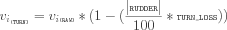
The configuration parameter turn_loss is a value in the range of [0,1]. When set to zero, there is no speed lost in any turn. When set to 1, there is a 100% speed loss when there is a maximum rudder. The default value is 0.85.
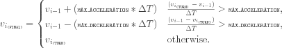
Step 3: In the last step, the candidate new speed,  , is compared with the incoming vehicle speed, vi-1. The elapsed time since the previous simulator iteration,
  , is used to calculate the acceleration or deceleration implied by the new speed. If the change in speed violates either the min_acceleration, or max_acceleration parameters, the speed is adjusted as follows:
Step 4: The final speed from the previous step is posted by the simulator as USM_SPEED, and is used the calculations of position and depth, described next.
5.2 Propagating the Vehicle Heading [top]
The vehicle heading is propagated primarily based on the current RUDDER value which is refreshed upon each iteration by reading the incoming mail on the MOOS variable DESIRED_RUDDER, and the elapsed time since the simulator previously updated the vehicle state,  . The change in heading my also be influenced by the THRUST value from the MOOS variable DESIRED_THRUST, and may also factor an external rotational speed.
The algorithm for updating the new vehicle heading proceeds as:
- Calculate
 , the new raw change in heading influenced only by the current rudder value.
- Calculate
 , an adjusted change in heading, based on the raw change in heading,
  , and the current THRUST value.
- Calculate
 , an adjusted change in heading considering external rotational speed.
- Calculate θi, the final new heading based on the calculated change in heading and the previous heading, and converted to the range of [0,359].
Step 1: In the first step, the new heading is calculated by the current RUDDER value:
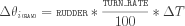
The TURN_RATE is an uSimMarine configuration parameter with the allowable range of [0,100]. The default value of this parameter is 70, chosen in part to be consistent with the performance of the simulator prior to this parameter being exposed to configuration. A value of 0 would result in the vehicle never turning, regardless of the rudder value.
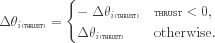
Step 2: In the second step the influence of the current vehicle thrust (from the MOOS variable DESIRED_THRUST) may be applied to the change in heading. The magnitude of the change of heading is adjusted to be greater when the thrust is greater than 50% and less when the thrust is less than 50%.
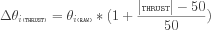
The direction in heading change is then potentially altered based on the sign of the THRUST:
Step 3: In the third step, the change in heading may be further influenced by an external rotational speed. This speed, if present, would be read at the outset of the simulator iteration from either the configuration parameter rotate_speed, or dynamically from the MOOS variable ROTATE_SPEED. The updated value is calculated as follows:

Step 4: In final step, the final new heading is set based on the previous heading and the change in heading calculated in the previous three steps. If needed, the value of the new heading is converted to its equivalent heading in the range [0, 359].

The simulator then posts this value to the MOOSDB as USM_HEADING.
5.3 Propagating the Vehicle Position [top]
The vehicle position is propagated primarily based on the newly calculated vehicle heading and speed, the previous vehicle position, and the elapsed time since updating the previous vehicle position,  .
.
The algorithm for updating the new vehicle position proceeds as:
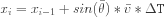
- Calculate the vehicle heading and speed used for updating the new vehicle position, with the heading converted into radians.
- Calculate the new positions,
 and
and  , based on the heading, speed and elapsed time.
- Calculate a possibly revised new position, factoring in any external drift.
Step 1: In the first step, the heading value,  , and speed value,
  used for calculating the new vehicle position is set averaging the newly calculated values with their prior values:


where s and c are given by:


The above calculation of the heading average handles the issue of angle wrap, i.e., the average of 359 and 1 is zero, not 180.
Step 2: The vehicle x and y position is updated by the following two equations:
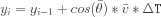
The above is calculated keeping in mind the difference in convention used in marine navigation where zero degrees is due North and 90 degrees is due East. That is, the mapping is as follows from marine to traditional trigonometric convention:  ,
,  ,
,  ,
,  .
.
Step 3: The final step adjusts the x, and y position from above, taking into consideration any external drift that may be present. This drift includes both the drift that may be directed from the incoming MOOS variables as described in Section 7. The drift components below are also a misnomer since they are provided in units of meters per second.


5.4 Propagating the Vehicle Depth [top]
Depth change in uSimMarine is simulated based on a few input parameters. The primary parameter that changes from one iteration to the next is the ELEVATOR actuator value, from the MOOS variable DESIRED_ELEVATOR. On any given iteration the new vehicle depth,  , is determined by:
The new vehicle depth is altered by the depth change rate,  , applied to the elapsed time,
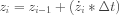
  , which is roughly equivalent to the apptick interval set in the uSimMarine configuration block. The depth change rate on the current iteration is determined by the vehicle speed and the ELEVATOR actuator value, and by the following three vehicle-specific simulator configuration parameters that allow for some variation in simulating the physical properties of the vehicle. The buoyancy_rate, for simplicity, is given in meters per second where positive values represent a positively buoyant vehicle. The max_depth_rate, and max_depth_rate_speed parameters determine the function(s) shown in Figure 5.1. The vehicle will have a higher depth change rate at higher speeds, up to some maximum speed where the speed no longer affects the depth change rate. The actual depth change rate then depends on the elevator and vehicle speed.
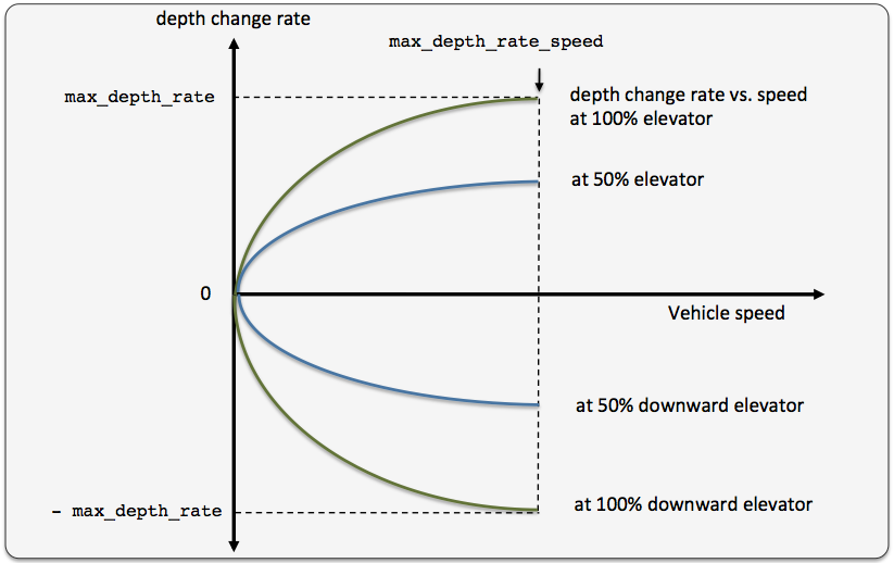
Figure 5.1: The relationship between the rate of depth change rate, given a current vehicle speed. Different elevator settings determine unique curves as shown.
The value of the depth change rate,  , is determined as follows:

Both fraction components in the above equation are clipped to [-1, 1]. When the vehicle is in reverse thrust and has a negative speed, this equation still holds. However, a vehicle would likely not have a depth change rate curve symmetric between positive and negative vehicle speeds. By default the value of buoyancy_rate is set to 0.025, slightly positively buoyant, max_depth_rate is set to 0.5, and max_depth_rate_speed is set to 2.0. The prevailing buoyancy rate may be dynamically adjusted by a separate MOOS application publishing to the variable BUOYANCY_RATE.
6 Propagating the Vehicle Altitude
The vehicle altitude is base solely on the current vehicle depth and the depth of the water at the current vehicle position. If nothing is known about the water depth, then USM_ALTITUDE is not published. The simulator may be configured with a default water depth:
default_water_depth = 100
This will allow the simulator to produce some altitude information if needed for testing consumers of USM_ALTITUDE information. Furthermore, the simulator subscribes for water depth information in the variable USM_WATER_DEPTH which could conceivably be produced by another MOOS application with access to bathymetry data and the vehicle's navigation position.
7 Simulation of External Drift
When the simulator updates the vehicle position as in equations provided in Section 5.3, it factors a possible external drift in the x and y directions, in the term EXTERNAL_DRIFT_X, and EXTERNAL_DRIFT_X respectively. The external drift may have two distinct components; a drift applied generally, and a drift applied due to a current field configured with an external file correlating drift vectors to local x and y positions. These drifts may be set in one of three ways discussed next.
7.1 External X-Y Drift from Initial Simulator Configuration [top]
An external drift may be configured upon startup by either specifying explicitly the drift in the x and y direction, or by specifying a drift magnitude and direction. Figure 7.1 shows two external drifts each with the appropriate configuration using either the drift_x and drift_y parameters or the single drift_vector parameter:
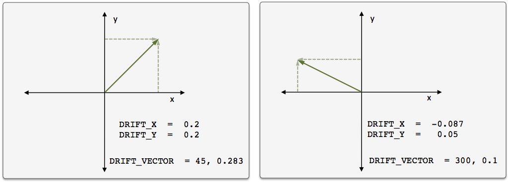
Figure 7.1: External Drift Vectors: Two drift vectors each configured with either the drift_x and drift_y configuration parameters or their equivalent single drift_vector parameter.
If, for some reason, the user mistakenly configures the simulator with both configuration styles, the configuration appearing last in the configuration block will be the prevailing configuration. If uSimMarine is configured with these parameters, these external drifts will be applied on the very first iteration and all later iterations unless changed dynamically, as discussed next.
7.2 External X-Y Drift Received from Other MOOS Applications [top]
External drifts may be adjusted dynamically by other MOOS applications based on any criteria wished by the user and developer. The uSimMarine application registers for the following MOOS variables in this regard: DRIFT_X, DRIFT_Y, DRIFT_VECTOR, DRIFT_VECTOR_ADD, DRIFT_VECTOR_MULT. The first three variables simply override the previously prevailing drift, set by either the initial configuration or the last received mail concerning the drift.
By posting to the USM_DRIFT_VECTOR_MULT variable the magnitude of the prevailing vector may be modified with a single multiplier such as:
   DRIFT_VECTOR_MULT = 2
   DRIFT_VECTOR_MULT = -1
The first MOOS posting above would double the size of the prevailing drift vector, and the second example would reverse the direction of the vector. The DRIFT_VECTOR_ADD variable describes a drift vector to be added to the prevailing drift vector. For example, consider the prevailing drift vector shown on the left in Figure 7.1, with the following MOOS mail received by the simulator:
DRIFT_VECTOR_ADD = "262.47, 15.796"
The resulting drift vector would be the vector shown on the right in Figure 7.1. This interface opens the door for the scripting changes to the drift vector like the one below, that crudely simulate a gust of wind in a given direction that builds up to a certain magnitude and dies back down to a net zero drift.
     DRIFT_VECTOR_ADD = 137, 0.25
     DRIFT_VECTOR_ADD = 137, 0.25
     DRIFT_VECTOR_ADD = 137, 0.25
     DRIFT_VECTOR_ADD = 137, 0.25
     DRIFT_VECTOR_ADD = 137, 0.25
     DRIFT_VECTOR_ADD = 137, -0.25
     DRIFT_VECTOR_ADD = 137, -0.25
     DRIFT_VECTOR_ADD = 137, -0.25
     DRIFT_VECTOR_ADD = 137, -0.25
     DRIFT_VECTOR_ADD = 137, -0.25
The above style script was described in the documentation for uTimerScript, where the uTimerScript utility was used to simulate wind gusts in random directions with random magnitude. The DRIFT_* interface may also be used by any third party MOOS application simulating things such as ocean or wind currents.
8 The ThrustMap Data Structure
A thrust map is a data structure that may be used to simulate a non-linear relationship between thrust and speed. This is configured in the uSimMarine configuration block with the thrust_map parameter containing a comma-separated list of colon-separated pairs. Each element in the comma-separated list is a single mapping component. In each component, the value to the left of the colon is a thrust value, and the other value is a corresponding speed. The following is an example mapping given in string form, and rendered in Figure 8.1.
thrust_map = "-100:-3.5, -75:-3.2, -10:-2, 20:2.4, 50:4.2, 80:4.8, 100:5"
Figure 8.1: A Thrust Map: The example thrust map was defined by seven mapping points in the string "-100:-3.5, -75:-3.2, -10:-2, 20:2.4, 50:4.2, 80:4.8, 100:5".
8.1 Automatic Pruning of Invalid Configuration Pairs [top]
The thrust map has an immutable domain of [-100, 100], indicating 100% forward and reverse thrust. Mapping pairs given outside this domain will simply be ignored. The thrust mapping must also be monotonically increasing. This follows the intuition that more positive thrust will not result in the vehicle going slower, and likewise for negative thrust. Since the map is configured with a sequence of pairs as above, a pair that would result in a non-monotonic map is discarded. All maps are created as if they had the pair 0:0 given explicitly. Any pair provided in configuration with zero as the thrust value will ignored; zero thrust always means zero speed. Therefore, the following map configurations would all be equivalent to the map configuration above and shown in Figure 8.1:
   thrust_map = -120:-5, -100:-3.5, -75:-3.2, -10:-2, 20:2.4, 50:4.2, 80:4.8, 100:5.0, 120:6
   thrust_map = -100:-3.5, -75:-3.2, -10:-2, 20:2.4, 50:4.2, 80:4.8, 90:4, 100:5.0
   thrust_map = -100:-3.5, -75:-3.2, -10:-2, 0:0, 20:2.4, 50:4.2, 80:4.8, 100:5.0
   thrust_map = -100:-3.5, -75:-3.2, -10:-2, 0:1, 20:2.4, 50:4.2, 80:4.8, 100:5.0
In the first case, the pairs "-120:-5" and "120:6" would be ignored since they are outside the [-100,100] domain. In the second case, the pair "90:4" would be ignored since its inclusion would entail a non-monotonic mapping given the previous pair of "80:4.8". In the third case, the pair "0:0" would be effectively ignored since it is implied in all map configurations anyway. In the fourth case, the pair "0:1" would be ignored since a mapping from a non-zero speed to zero thrust is not permitted.
8.2 Automatic Inclusion of Implied Configuration Pairs [top]
Since the domain [-100,100] is immutable, the thrust map is altered a bit automatically when or if the user provides a configuration without explicit mappings for the thrust values of -100 or 100. In this case, the missing mapping becomes an implied mapping. The mapping 100:v is added where v is the speed value of the closest point. For example, the following two configurations are equivalent:
     thrust_map = -75:-3.2, -10:-2, 20:2.4, 50:4.2, 80:4.8
     thrust_map = -100:-3.2, -75:-3.2, -10:-2, 20:2.4, 50:4.2, 80:4.8, 100:4.8
8.3 A Shortcut for Specifying the Negative Thrust Mapping [top]
For convenience, the mapping of positive thrust values to speed values can be used in reverse for negative thrust values. This is done by configuring uSimMarine with thrust_reflect=true, which is false by default. If thrust_reflect is false, then a speed of zero is mapped to all negative thrust values. If thrust_reflect is true, but the user nevertheless provides a mapping for a negative thrust in a thrust map, then the thrust_reflect directive is simply ignored and the thrust map is used instead. For example, the following two configurations are equivalent:
thrust_map = -100:-5, -80:-4.8, -50:-4.2, -20:-2.4, 20:2.4, 50:4.2, 80:4.8, 100:5
and
     thrust_map = 20:2.4, 50:4.2, 80:4.8, 100:5
     thrust_reflect = true
8.4 The Inverse Mapping - From Speed To Thrust [top]
Since a thrust map only permits configurations resulting in a non-monotonic function, the inverse also holds (almost) as a valid mapping from speed to thrust. We say "almost" because there is ambiguity in cases where there is one or more plateau in the thrust map as in:
thrust_map = -75:-3.2, -10:-2, 20:2.4, 50:4.2, 80:4.8
In this case a speed of 4.8 maps to any thrust in the range [80,100]. To remove such ambiguity, the thrust map, as implemented in a C++ class with methods, returns the lowest magnitude thrust in such cases. A speed of 4.8 (or 5 for that matter), would return a thrust value of 80. A speed of -3.2 would return a thrust value of -75. The motivation for this way of disambiguation is that if a thrust value of 80 and 100, both result in the same speed, one would always choose the setting that conserves less energy. Reverse mappings are not used by the uSimMarine application, but may be of use in applications responsible for posting a desired thrust given a desired speed, as with the pMarinePID application.
8.5 Default Behavior of an Empty or Unspecified ThrustMap [top]
If uSimMarine is configured without an explicit thrust_map or thrust_reflect configuration, the default behavior is governed as if the following two lines were actually included in the uSimMarine configuration block:
     thrust_map     = 100:5
     thrust_reflect = false
The default thrust map is rendered in Figure 8.2.
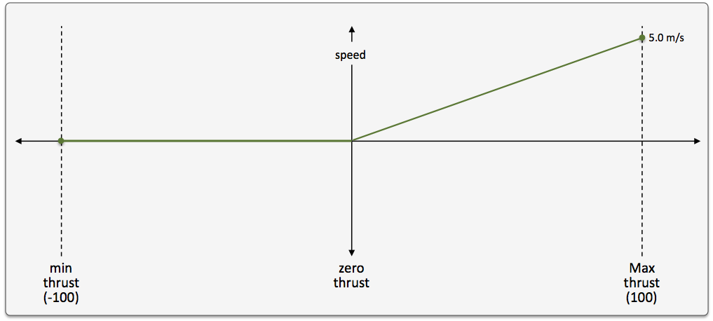
Figure 8.2: The Default Thrust Map: This thrust map is used if no explicit configuration is provided.
This default configuration was chosen for its reasonableness, and to be consistent with the behavior of prior versions of uSimMarine where the user did not have the ability to configure a thrust map.
Page built from LaTeX source using texwiki, developed at MIT. Errata to issues@moos-ivp.org. Get PDF