Aquaticus Robot Platform - The Heron USV
Maintained by: mikerb@mit.edu  Get PDF
1 Heron Overview
1.1 MIT PavLab Mechanical Modifications to the Robot
1.1.1 The Payload Autonomy Box and Battery
1.1.2 The Payload Cover and E-Stop Button
1.1.3 GPS and IMU Mount
1.2 Information Generated and Logged from the Robots
1.2.1 Robot Data Logs and Vehicle Track Information
1.2.2 Autonomy Mode Information
1.2.3 Inter-Vehicle Messaging Information
1.3 Robot Safety
1.3.1 Collision Avoidance
1.3.2 Operation Area Bounding Box
1.3.3 Remote Control in an Emergency
1 Heron Overview

The robotic platform is a commercially available unmanned surface vehicle, USV, the Heron M300 made by Clearpath Robotics, shown in Figure 1.1. It is augmented with a payload computer running GNU/Linux and the open source MOOS-IvP autonomy software from MIT. It is capable of a top speed of 1.8 meters per second (4 miles per hour). It is equipped with a GPS, compass, and WiFi.

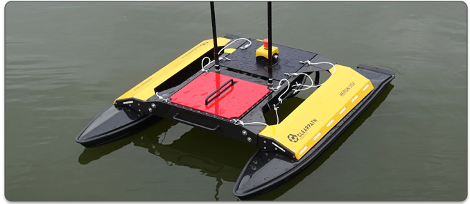
Figure 1.1: The Heron M300: The Heron M300 unmanned surface vehicle serves at the robotic teammate.


1.1 MIT PavLab Mechanical Modifications to the Robot [top]
A number of mechanical modifications were made to the MOKAI to better suit our uses at MIT. The key mechanical modificications:

- The payload autonomy box and battery
- The payload cover and E-Stop button
- The GPS anntenna location and mount
- The IMU mount location


1.1.1 The Payload Autonomy Box and Battery [top]
The Herons autonomy system is run from the payload computer, separate from the main vehicle computer shipped with the Heron. The payload autonomy computer is situated in a water-tight box that we call the payload autonony box (PABLO). This box contains a Raspberry PI computer, with a water tight Ethernet connector for communications to the Heron main vehicle computer, and a USB water tight connector for power. The PABLO is powered by a commercial battery typically used for travel power for cell phone charging, providing a 5V supply. This battery resides in its own water tight box with a connector leading directly to the PABLO computer box. This arrangement is shown below in Figure 1.2

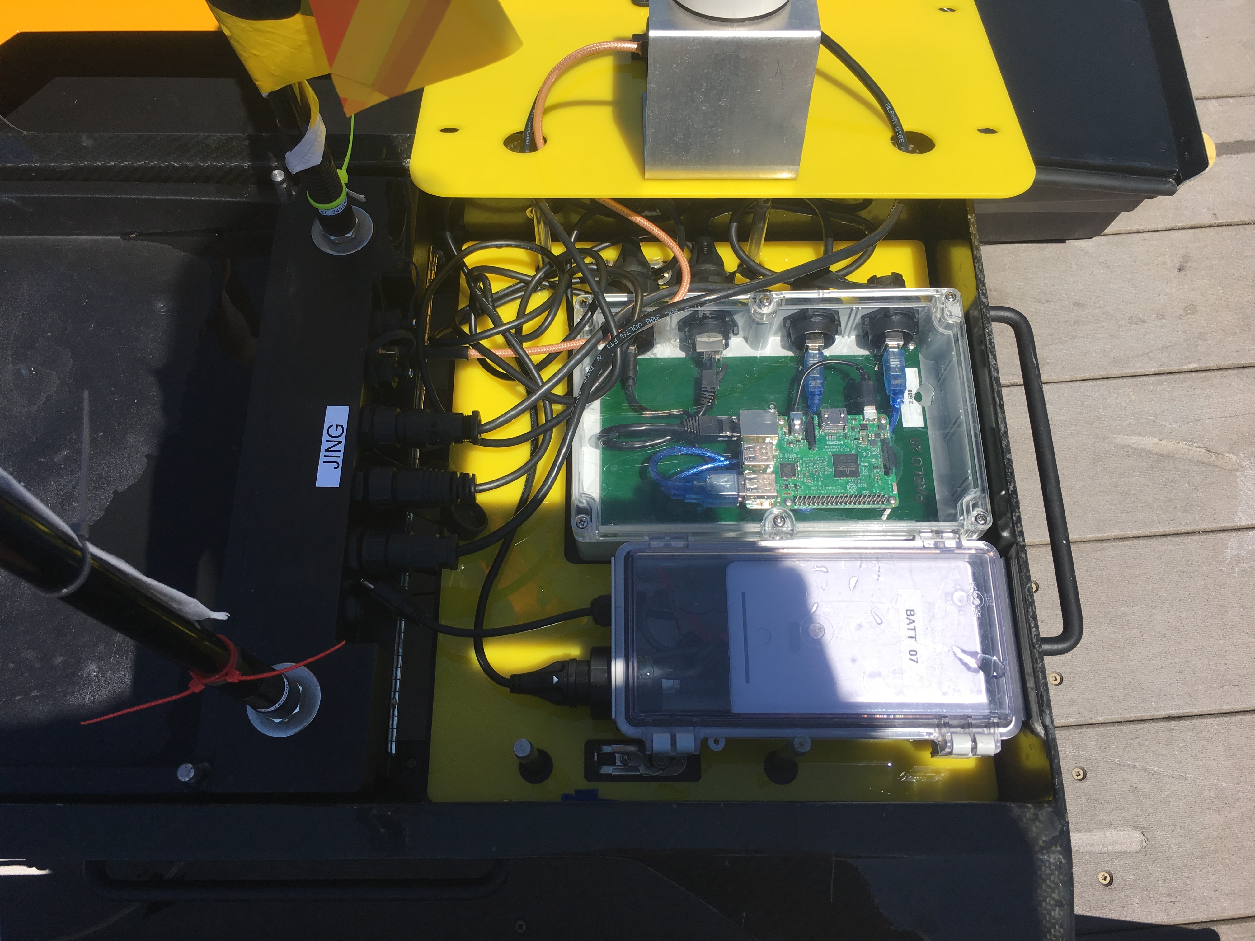
Figure 1.2: The Heron Payload Section: The Heron robot has a paylod section where we mount our payload autonomy computer and the computer power supply in separate water tight boxes.


The yellow plate shown in the figure underneath the PABLO and battery boxes, is a cutout plate to guide the placement of the boxes within the payload section. The cabling and connector locations of both boxes was designed to precisely fit the palyoad section in the layout cut into the bottom plate.


1.1.2 The Payload Cover and E-Stop Button [top]
The orginal payload shipped to MIT was a simple metal cover with provisions for mounting the E-Stop button. The E-stop button itself was a non-standard feature (at least at the time) added for extra safety. Ultimately we decided to move away from this cover to the one shown on the right, which is laser cut to accommodate additional components such as the GPS receiver and the IMU.

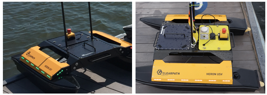
Figure 1.3: The Heron Payload Cover: The original payload cover is shown on the left, only having the E-Stop button. The MIT modified cover is shown on the right, with the E-Stop button, IMU, and GPS receiver. The cover itself is a laser-cut cover with mounting holes with more tolerance than the original cover.


The original cover was also hard to place back onto the vehicle. The four holes in the cover needed to go over the four posts on the body. The holes had very little tolerance for a less-than-perfect alignment of the four posts.


1.1.3 GPS and IMU Mount [top]
The orginal Herons were shipped with the GPS receiver mounted inside the computer box, underneath the battery on the forward part of the vehicle. This unfortanately provide very poor performance, poor SNR, and very poor estimation of vehicle heading. Later fixes by Clearpath moved the GPS receiver to be on the frame of the vehicle between the battery and the payload cover. Ultimately we decided to build a mount for the GPS receiver, on the payload cover as shown in Figure 1.4. The metal plate also provides a bit of a backplane for the receiver, as recommended by the GPS manufacturer. Performance in this mode has been more than sufficient.

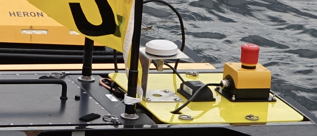
Figure 1.4: The Heron GPS Receiver: The GPS receiver has been moved on the MIT vehicles to be on a separate mounting bracket on the payload cover, which also provides a bit of a backplane for better performance.


The IMU unit was originally located underneath the Heron. It is now mounted on top of the payload autonomy cover as shown above in the figure, between the GPS receiver and the E-Stop button.
Both the GPS and IMU are connected directly to the main vehicle computer of the Heron. The payload autonomy computer receives this information from the Heron main computer via an NMEA interface.


1.2 Information Generated and Logged from the Robots [top]
The Heron robots typically are running in an autonomous mode using the MOOS-IvP software running in the payload autonomy computer. They are typically in regular contact with a shoreside computer, to both provide regular status updates to operators, and to allow the operators to alter the robot autonomy mode, e.g., to recall them home, or put them into temporary station-keeping mode or any other defined autonomy mode on the robot.

The Herons will typically run a logger application logging all data produced in the MOOS-IvP autonomy system. This application is call pLogger and produces a time-stamped folder of data. The key file is called an alog file, as it ends with the suffix .alog. A few key components of this file are described below.

1.2.1 Robot Data Logs and Vehicle Track Information [top]
The robot log files will contain the track information for the robot

- NAV_X, NAV_Y: The robot local X-Y position
- NAV_HEADING, NAV_SPEED: The robot heading and speed information.
- NODE_REPORT: A string report containing all of the above in one single message.


The NODE_REPORT variable is shared from the vehicle to the shoreside to enable viewing on a command-and-control display. It also typically shared real-time to other vehicles on the field to allow vehicles to perform collision avoidance.


1.2.2 Autonomy Mode Information [top]
The robot autonomy mode is also logged as the mission progresses. Typically this is logged simply in the varible MODE. The set of modes available for a mission may vary, depending on how the autonomy designer configured the helm. The set of modes will depend on other mission variables and commands from the shoreside or other robots. These variables are also logged and available for later analysis.


1.2.3 Inter-Vehicle Messaging Information [top]
In addition to command-and-control messages from the shoreside operators, robots may also receive messages from other vehicles also using MOOS. An inter-vehicle message comes in the variable NODE_MESSAGE. A message has two key parts, the name of the local MOOS variable to be modified, and the value to be applied to this MOOS variable.


1.3 Robot Safety [top]
During normal operation, several measures are taken to ensure the robots operate safely in terms of collision with other vessels, the docks, and remaining in their operation area.

1.3.1 Collision Avoidance [top]
The robots will often need to perform collision avoidance on the river with other vehicles, robots or otherwise. Currently the Herons are not equipped with any sensors for detecting the position, heading or speed of other vessels. All vessels like the one in the below figure, are equipped with their own GPS and compass and routinely report their positions to other nearby vehicles on the test range.

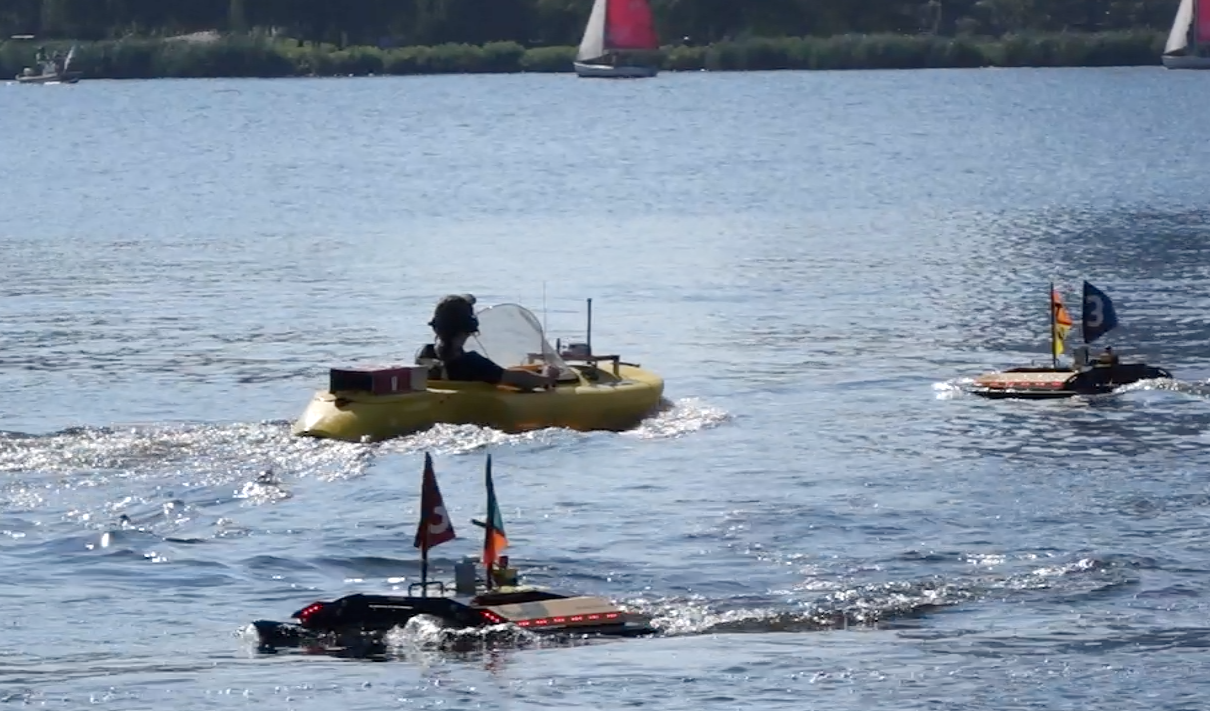
Figure 1.5: Collision Avoidance Situations: The robots will often encounter the need to perform collision avoidance on the river.


Collision avoidance on the robots is accomplished within the IvP Helm using a collision avoidance behavior based on the COLREGS. More information on this can be found in the helm documentation. But in short, vehicles won't simply maneuver to avoid, but will maneuver in the manner prescribed by the COLREGS. For example, in head-on situations, both vehicles will turn to the right, passing each other on their port side.


1.3.2 Operation Area Bounding Box [top]
Our Robots are also typically operating within a given operation area. For Aquaticus, this area is described here:
http://oceanai.mit.edu/aquaticus/oparea
The operation area will typically have a hard and a soft boundary. When it goes outside the soft boundary, it has the chance to switch autonomy modes to recover back into the main operation area. When it goes outside the hard boundary, the robot will simply shut off its propulsion.


1.3.3 Remote Control in an Emergency [top]


Page built from LaTeX source using texwiki, developed at MIT. Errata to issues@moos-ivp.org.
 Get PDF